Electric drill with charge state and directional indicator

a technology of directional indicators and electric drills, which is applied in the direction of portable power-driven tools, dynamo-electric machines, electrical apparatus, etc., can solve the problems of limited time for battery-powered tools, alternating current powered tools, and considerable expense for batteries, so as to achieve maximum illumination efficiency and high efficiency in lighting

Inactive Publication Date: 2010-03-25
INNOVATIVE CONCEPTS
View PDF4 Cites 16 Cited by
  • Summary
  • Abstract
  • Description
  • Claims
  • Application Information

AI Technical Summary

Benefits of technology

[0008]It will be understood that the prevention of such rotation inadvertently in the wrong direction will be effective to preserve battery life and prevent damage to drill bits.
[0014]Moreover, if the electric drill is recharged, the charge followed by discharge followed by recharge operation has the effect of prematurely shortening the life of the battery. Besides being associated with significant economic costs, premature disposal of rechargeable batteries, which have a limited charge / recharge cycle life, does unnecessary environmental damage.
[0027]In accordance with the invention, high efficiency in lighting is provided by illuminating principally those areas of the workpiece which are likely to be visible to the user of the tool and / or likely to need illumination.
[0028]Importantly, as has been recognized in accordance with the invention, the positioning of lights aligned with the bottom of the drill and its handle suffers from the inefficiency of not illuminating that portion of the workpiece adjacent the top of the drill, i.e. that portion of the workpiece opposite the handle. Since the most visible part of the workpiece is that portion of the workpiece adjacent the left side of the drill in the case of a right-handed user and adjacent the right side of the drill in the case of a left-handed user, and the second most visible part is that portion of the workpiece opposite the handle, maximum efficiency of illumination and provision of the tool which will work well for both right-handed and left-handed users is served by the provision of lighting on opposite sides of the drill and adjacent the top of the drill.
[0030]Still further efficiency can be provided by the provision of switches associated with each of the lights, so that illumination may be tailored to a particular user's style or a particular job's requirements.

Problems solved by technology

First of all, these battery-powered tools may only be operated for a limited amount of time.
In addition, batteries, while they do provide efficiency of effort as compared to conventional alternating current powered tools, do involve considerable expense.
In addition, proper disposal of the batteries carries added costs.
In connection with this, it is also noted that the rechargeable batteries do have a limited life in terms of the number of times which they may be recharged.
More particularly, reversible drills of the battery powered variety may, by mistake, be powered with a drill bit going in the wrong direction.
This results in loss of power and depletion of battery life.
Many times, this may occur for a prolonged period of time and is only discovered when the lack of progress, for example, in drilling a hole becomes apparent.
In addition, operation of a drill in reverse against the workpiece may cause a drill bit to overheat.
If a screw or bolt is properly seated in a workpiece, operation in the forward direction may cause it to strip threads cut in the workpiece.
However, markings may be difficult to read, and with time, may chip away.
In addition, such markings are typically on or adjacent to the drill actuation switch and are thus not easily visible, because of their position, and may even be covered by the fingers of the individual using the battery-powered drill.

Method used


Image

  • Electric drill with charge state and directional indicator
  • Electric drill with charge state and directional indicator
  • Electric drill with charge state and directional indicator

Examples


Embodiment Construction

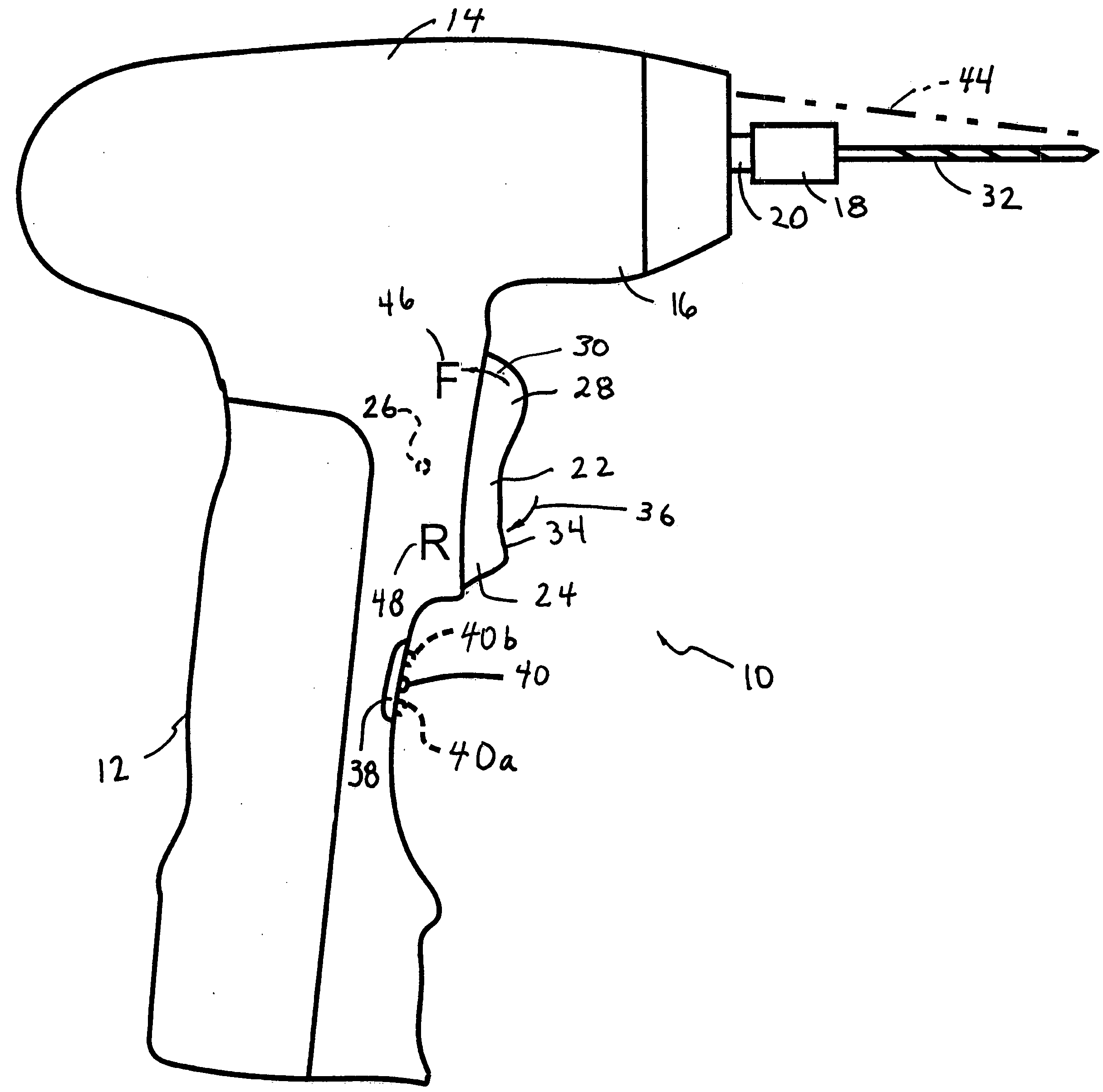
[0041]As illustrated in FIG. 1, an electric drill 10 constructed in accordance with the present invention is illustrated.

[0042]Drill 10 includes a handle portion 12 and a driver portion 14. Driver portion 14 comprises a neck 16. A chuck 18, of conventional design, is mounted on a spindle 20. In accordance with the preferred embodiment, it is contemplated that chuck 18 may be any conventional hex socket chuck, as a wide variety of tool bits having mountings suitable for such chucks are readily available on the market.

[0043]Alternatively, a multi-fingered chuck, for example one of the type using a serrated sleeve may be employed. Alternatively, a multi-fingered chuck employing a conical gear pin key (such as that sold by Jacobs Manufacturing) may also be advantageously employed in accordance with the present invention. Spindle 20 is coupled to a motor, not illustrated, but of conventional design, housed within driver portion 14. In accordance with the invention, drill 10 is capable of...


PUM


Abstract

In accordance with the invention, a drill comprises a drill housing with a handle portion and a driver portion. An electrical drill motor is located in the driver portion. The drill motor has an output shaft for coupling output rotary power. An electrical switch controls the operation of the drill motor. The electrical switch it is located on the handle portion of the drill housing. A chuck is coupled to the output shaft of the drill motor. A display combines information or state of charge of the battery and drill direction without unduly compromising battery life.

Description

TECHNICAL FIELD[0001]The invention relates to multifunction indicators for portable drills, particularly those powered by batteries, such as rechargeable batteries.CROSS REFERENCE TO RELATED APPLICATIONS[0002]Not applicable.STATEMENT REGARDING FEDERALLY SPONSORED RESEARCH OR DEVELOPMENT[0003]Not applicable.BACKGROUND OF THE INVENTION[0004]Electrically powered drills remain one of the mainstays of every tool box, whether it be that of a homeowner or construction professional. Even going back to the 1950s, electrical drills were in very common use in the home, with companies like Sears Roebuck & Co. and others turning out high quality products at very modest prices in what was then a very old technology.[0005]Indeed, the most modern form of the electric drill, namely a pistol shaped device with a multi-fingered chuck that could be tightened using a conical gear key, followed closely the development of these chucks by the Jacobs Manufacturing Co. in or about 1902. Except for the introd...

Claims


Application Information

Patent Timeline
Patent Type & Authority Applications(United States)
IPC IPC(8): H02K7/14
CPCB25F5/021B25F5/00
Inventor CANINO, SERAFINOGELORMINO, SCOTT
Owner INNOVATIVE CONCEPTS
Why Eureka
Try Eureka