Method and apparatus for encoding image

a technology of image encoding and image, applied in the direction of electrical equipment, instruments, computing, etc., can solve the problems of inapplicability of the method proposed by s. w. wu, inability to perform inefficient encoding, and relatively large process cos

Inactive Publication Date: 2010-03-25
KK TOSHIBA
View PDF5 Cites 41 Cited by
  • Summary
  • Abstract
  • Description
  • Claims
  • Application Information

AI Technical Summary

Problems solved by technology

However, with the method proposed by Y. Chen, it cannot be said that the quantization matrix is optimally designed from a view point of the encoding efficiency because the actual code amount is not considered in the method, leaving a possibility of performing an inefficient encoding.
Furthermore, the method proposed by S. W. Wu is not practically useful because a re-encoding process is required with respect to each frequency position which necessitates a relatively large process cost.
In addition, the technology proposed by J. Lee is not practically useful, either, because a massive number of combinations of parameters necessary for the modeling are present which necessitates a relatively large process cost similarly to the method proposed by S. W. Wu.

Method used


Image

  • Method and apparatus for encoding image
  • Method and apparatus for encoding image
  • Method and apparatus for encoding image

Examples


first embodiment

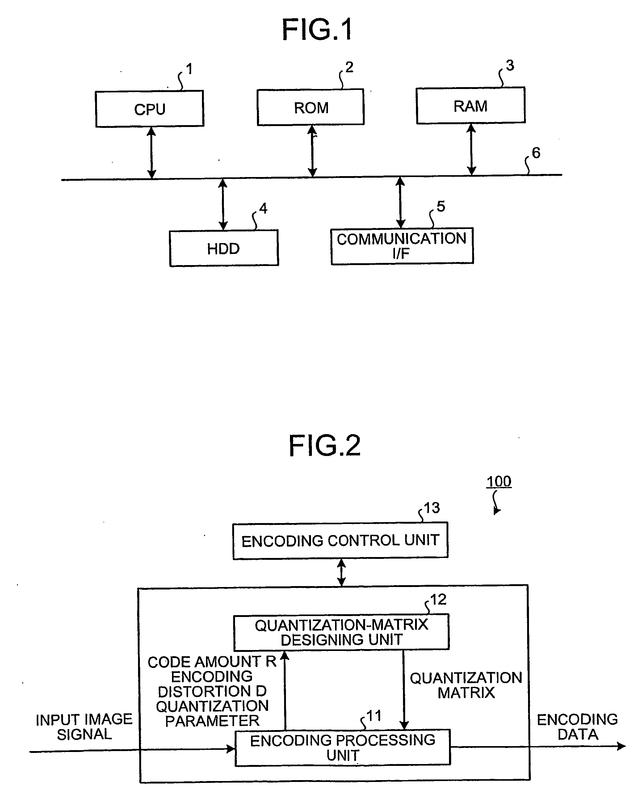
[0033]FIG. 1 is a schematic diagram of an image encoding apparatus 100 according to a As shown in FIG. 1, the image encoding apparatus 100 includes a central processing unit (CPU) 1, a read only memory (ROM) 2, a random access memory (RAM) 3, a hard disk drive (HDD) 4, and a communication interface (I / F) 5, which are connected each other via a bus 6.

[0034]The CPU 1 performs an overall control of the components constituting the image encoding apparatus 100 by using a predetermined area of the RAM 3 as a working area and executing various processes (for example, an image encoding process which will be described later) in cooperation with various control programs stored in advance in the ROM 2 and the HDD 4 (hereinafter, collectively referred to as “a storing unit”).

[0035]The ROM 2 stores therein various programs for controlling the image encoding apparatus 100 and various pieces of setting information in a read-only manner.

[0036]The RAM 3 is a storage device such as a synchronous dyn...

second embodiment

[0129]An image encoding apparatus is explained below.

[0130]FIG. 16 is a block diagram illustrating a functional configuration of an image encoding apparatus 200 according to the second embodiment. As for a function unit that is different from the first embodiment, an area dividing unit 14 is added. In the same manner as the other function units, the CPU 1 controls each of the components according to a predetermined program stored in advance in the storing unit so that the area dividing unit 14 is generated in the RAM 3.

[0131]The area dividing unit 14 has a function of dividing the area in the encoding frame by using a feature amount of the input image signal. The quantization-matrix designing unit 12 designs the quantization matrix by using the code amount R and the encoding distortion D obtained from a tentative encoding by the encoding processing unit 11. Therefore, an optimum solution of the quantization matrix is different depending on a level of the encoding. By performing an ...

third embodiment

[0150]As describe above, the switch 153 is controlled dynamically according to the phase of the image encoding apparatus 300. Therefore, because the quantization matrix can be designed using an image reduced through the down-sampling unit 151 and the post-filter unit 152 when designing the quantization matrix, and the encoding can be performed on the input image when performing the actual encoding, it is possible to greatly reduce a time for designing the quantization matrix.

[0151]Although the simple one-pixel skipping down-sampling method is explained according to the third embodiment, the present invention is not limited to this scheme. For instance, a sophisticated down sampling can be used according to the signal characteristic and the circuit characteristics. Furthermore, the reduced image is not necessarily limited to the ¼ reduced image, but a ½ reduced image or a ⅛ reduced image can be used as the reduced image. However, as the image size becomes smaller, a degradation of t...


PUM


Abstract

A value of a selection parameter is sequentially set from among a plurality of parameters included in a modeling equation to derive a quantization matrix. A value of each of the parameters is sequentially derived based on a code amount and an encoding distortion obtained from an encoding using a quantization matrix generated from an updated parameter set.

Description

TECHNICAL FIELD[0001]The present invention relates to an image encoding method, and an image encoding apparatus for quantization and dequantization of an image signal.BACKGROUND ART[0002]In the ITU Telecommunication Standardization Sector (ITU-T) T.81 and the International Standards Organization (ISO) / International Electrotechnical Commission (IEC) 10918-1 recommended by the ITU-T and the ISO / IEC (hereinafter, “Joint Photographic Experts Group (JPEG)”), a quantization is performed uniformly across an entire frequency domain when performing the quantization (encoding) of transform coefficients on the same quantization scale. In the JPEG, because the human visual feature is relatively insensitive to a high-frequency domain, a coarse quantization is generally performed for a high-frequency component compared with a low-frequency component, by performing a weighting with respect to each frequency domain using a coefficient table called a quantization matrix. The quantization matrix usin...

Claims


Application Information

Patent Timeline
Patent Type & Authority Applications(United States)
IPC IPC(8): G06K9/00H04N19/126H04N19/134H04N19/115H04N19/136H04N19/139H04N19/14H04N19/146H04N19/147H04N19/154H04N19/189H04N19/19H04N19/196H04N19/423H04N19/46H04N19/503H04N19/593H04N19/60H04N19/61H04N19/625H04N19/70H04N19/91
CPCH04N19/147H04N19/149H04N19/126H04N19/60H04N19/115
Inventor TANIZAWA, AKIYUKICHUJOH, TAKESHI
Owner KK TOSHIBA
Why Eureka
Try Eureka