Method to extract target signals of a known type from raw data containing an unknown number of target signals, intereference, and noise

a target signal and raw data technology, applied in the field of data processing, can solve the problems of not being able to work on purification of oil debris signal from collected noisy data not being able to report the work on purification of oil debris signal with the effect of vibration, so as to enhance the capability of a sensor and reduce any intrinsic noise signals

Inactive Publication Date: 2010-03-25
UNIVERSITY OF OTTAWA
View PDF19 Cites 24 Cited by
  • Summary
  • Abstract
  • Description
  • Claims
  • Application Information

AI Technical Summary

Benefits of technology

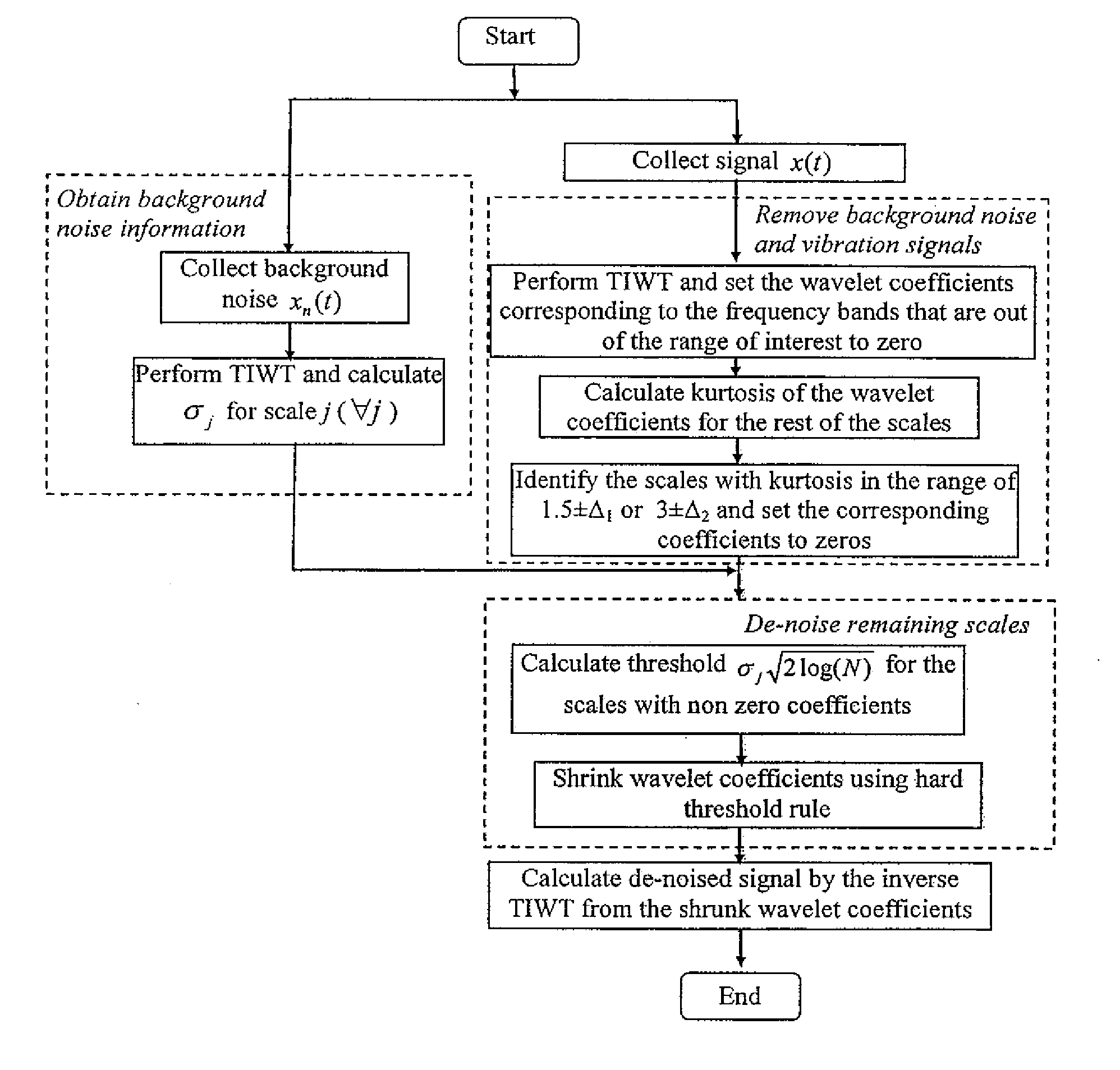
[0008]In another aspect of the technique, there is provided a method of enhancing the capability of a sensor for sensing a particle or bubble in a fluid flow, the sensor being adapted for generating transient target signals when particles or bubbles in the fluid pass through the sensor, which comprises the steps of (a) defining quantifiable signatures of the target signals, having a known frequency range of the target signals and a known kurtosis value range of wavelet coefficients of respective wavelet scales of interest that reflect a transient nature of the target signals; (b) defining quantifiable signatures of interfering signals and intrinsic noise signals, having two known kurtosis value ranges of wavelet coefficients of each of wavelet scales that correspond to the interfering signals and correspond to the intrinsic noise signals respectively; (c) obtaining a raw data sample signal in a time domain from the sensor in use for monitoring the fluid flow; (d) applying a Time-Invariant Wavelet Transform (TIWT) to said raw data sample signal to effect a decomposition of said raw data sample signal into a plurality of data sets in a form of wavelet coefficients of respective wavelet scales; (e) processing the data sets to calculate a kurtosis value for each data set to compare the kurtosis value for each data set with the kurtosis value range defined in step (a) or the kurtosis value ranges defined in step (b), in order to identify a first group of data sets which display the signatures representing the interfering signals and the intrinsic noise signals and a second group of data sets which display the signatures representing the target signals, and then setting the data sets of the first group to zero; (f) applying a thresholding rule to process the data sets of the second group in order to reduce any intrinsic noise signals which remain in the data sets of the second group; and (g) constructing a processed output signal by applying an inverse transform to the data sets processed in step (e) and (f).

Problems solved by technology

However, most oil debris sensors are not only sensitive to metal particles but also susceptible to various noises and vibrations.
The first issue is how to use an existing sensor to detect the weakest possible debris or particle signals that are concealed in noise, such that quick responses to incipient failures can be achieved.
The size of a particle that can be detected is mainly limited by background noise, while the challenge of eliminating spurious signals lies in their similarity to particle signals.
Though de-noising has been studied by many researchers in various fields, work on purification of oil debris signal from the collected noisy data with the effects of vibration has not yet been reported in the accessible literature.
However, most of the existing de-noising methods focus on the reduction of background Gaussian noise only, and thus cannot be directly applied to purify the collected oil debris signals.

Method used


Image

  • Method to extract target signals of a known type from raw data containing an unknown number of target signals, intereference, and noise
  • Method to extract target signals of a known type from raw data containing an unknown number of target signals, intereference, and noise
  • Method to extract target signals of a known type from raw data containing an unknown number of target signals, intereference, and noise

Examples


Embodiment Construction

[0022]The definition of the following terms are applicable throughout the specification and the claims of this application.

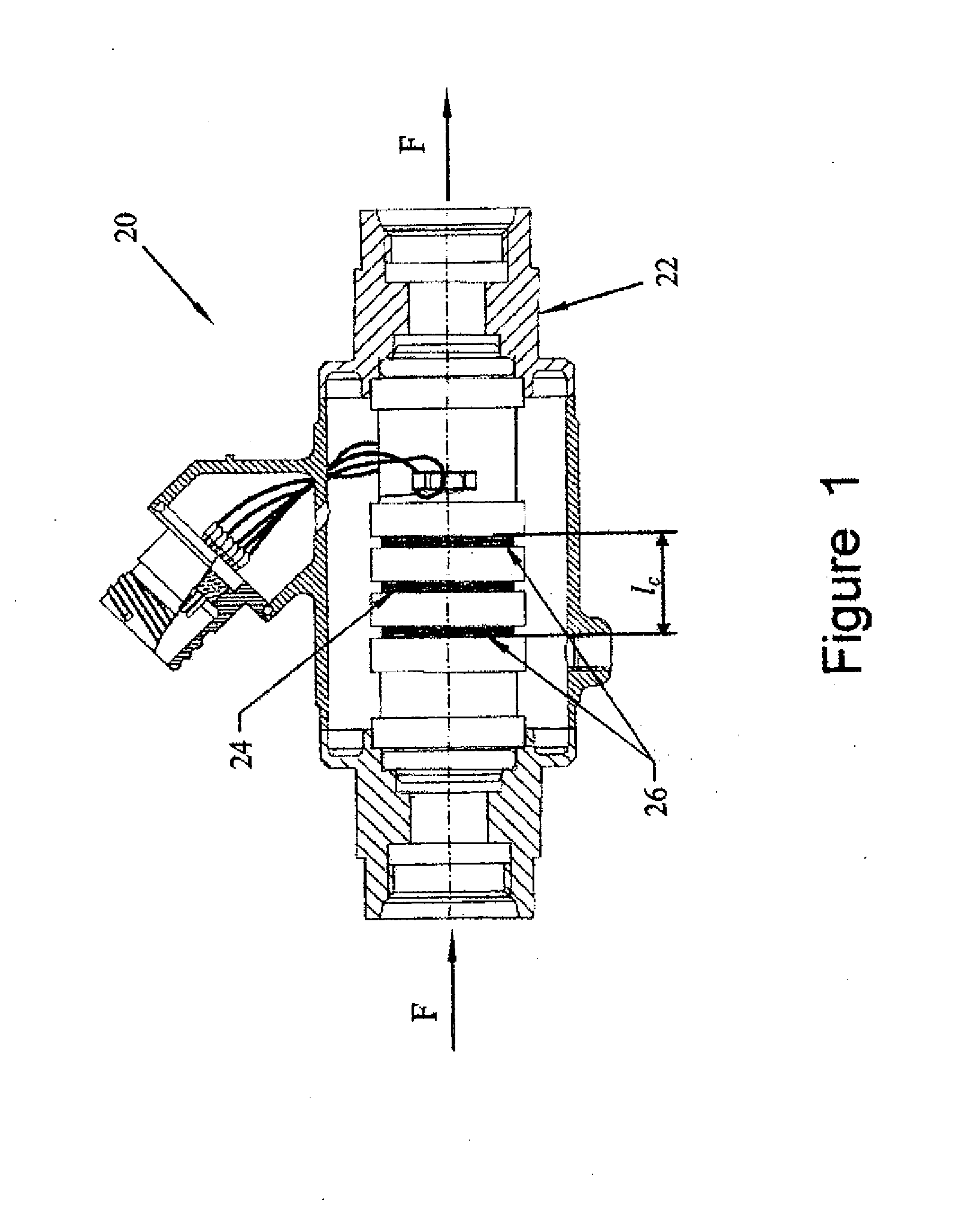
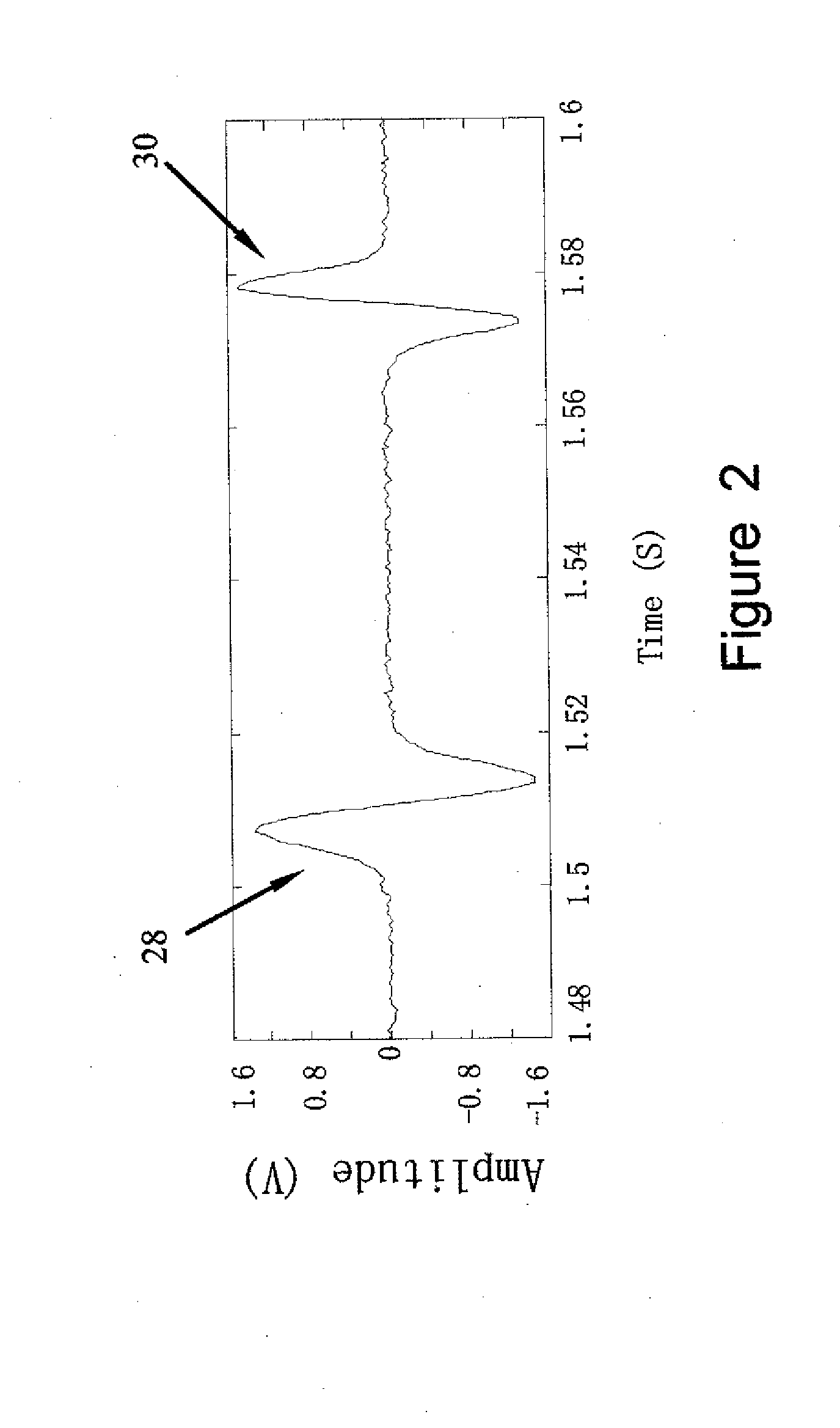
[0023]A target signal is a signal which is sought. According to the described technique, target signals must be of finite duration, and must possess a known characteristic profile. Target signals may however occur at random intervals. In the case of an oil-debris sensor, a target signal is a transient signal created by the oil-debris sensor in response to the passage of a suspended particle passing through the sensor.

[0024]An intrinsic noise signal refers to a minimum, unavoidable noise of a sensor and measurement system. The intrinsic noise signal is the signal obtained from the sensor in controlled conditions. These conditions are contrived so as to possess no target signals and no significant interfering signals. In the case of an oil-debris sensor, the intrinsic noise signal is obtained from the sensor when operating in quiet laboratory conditions, without t...


PUM


Abstract

A signal analysis method extracts transient target signals of known type from a raw data source signal that contains an unknown number of target signals. The method can enhance the analysis of data obtained from in-line oil-debris sensors. The method comprises steps of: defining signatures of the known target signal, and of at least one of the intrinsic noise and interfering signals; performing a mathematical transform that decomposes the raw data into distinct data sets; using the signal signatures to identify and nullify the data sets containing noise and interfering signal signatures; using the target signal signatures to identify the data sets containing target signal components, or may further use a thresholding rule to remove intrinsic noise from said data sets, and finally applying the inverse transform to the processed data sets in order to reconstruct an enhanced output signal.

Description

FIELD OF THE TECHNIQUE[0001]The technique generally relates to data processing and more particularly, to the improvement of in-line oil debris sensor capability.BACKGROUND OF THE TECHNIQUE[0002]Early detection of mechanical damage by continuously monitoring the metallic debris in lubrication oil of various mechanical systems such as aircraft engines, is extremely important for fault diagnosis, maintenance decision-making, and accident prevention. In-line oil debris detection sensors have attracted attention recently because of the advantage of monitoring machine conditions continuously and eliminating some of the laboratory work required in off-line oil sample analysis. However, most oil debris sensors are not only sensitive to metal particles but also susceptible to various noises and vibrations. Therefore, there are two major issues to be addressed in real time oil debris detection. The first issue is how to use an existing sensor to detect the weakest possible debris or particle ...

Claims


Application Information

Patent Timeline
Patent Type & Authority Applications(United States)
IPC IPC(8): G06F19/00G06F15/00
CPCG06K9/00516G05B23/0229G06F2218/06
Inventor LIANG, MINGYEAP, TET HINFAN, XIANFENGBOZCHALOOI, IMAN SOLTANI
Owner UNIVERSITY OF OTTAWA
Why Eureka
Try Eureka