Revolution counter for turning assemblies

a technology of turning assembly and counter, which is applied in the direction of converting sensor output, instruments, measurement devices, etc., can solve the problems of moving and/or stationary parts that must be designed, removed or repaired, and achieve the effect of convenient utilization

Active Publication Date: 2010-04-01
THE BOEING CO
View PDF0 Cites 8 Cited by
  • Summary
  • Abstract
  • Description
  • Claims
  • Application Information

AI Technical Summary

Benefits of technology

[0011]In a preferred embodiment, the device body has an intermediate housing connecting with the first portion which contains the memory counter circuitry. The adapter shaft has splined input and output ends that can be interfaced interchangeably with any matched driving part (such as a torque wrench or a nut runner) and driven part, and thus can be easily utilized with different kinds of wrenches and on different kinds of turning assemblies.
[0012]For use in the aircraft industry, the revolution counter tool can be used for keeping track of the number of revolutions of the torque tubes for installing or resetting slats or flaps of the wings of an airplane. The splined shaft of the tool can be plugged into any gearbox for the leading or trailing edges that run the control surfaces to keep track of how far a mechanic has moved a control surface so that it can be returned to the exact same location to re-align the control surface after rework or repairs are accomplished. This can prevent contact damage to the gearboxes for the control surfaces during operational use of the airplane and the attendant need for repair.

Problems solved by technology

One disadvantage with these prior types of devices is that the moving and / or stationary parts must be designed specifically to attach to the rotating structures the devices are used to measure.
If the control surfaces are run too far either in or out, the range of motion of the control surfaces during operational use may result in mechanical stops that can cause damage to the gearbox, resulting in the need to remove or repair the gearbox.

Method used


Image

  • Revolution counter for turning assemblies
  • Revolution counter for turning assemblies
  • Revolution counter for turning assemblies

Examples


Embodiment Construction

[0020]In the following detailed description, certain preferred embodiments for a revolution counter device are described to illustrate the principles of the disclosure in the specific application environment of adjusting control surfaces for flap positions in the aircraft industry. It will be recognized by one skilled in the art that the present disclosure may be practiced in other analogous applications or environments and / or with other analogous or equivalent variations of the illustrative embodiments. It should also be noted that those methods, procedures, components, or functions which are commonly known to persons of ordinary skill in the field of the invention are not described in detail so as avoid unnecessarily obscuring a concise description of the preferred embodiments.

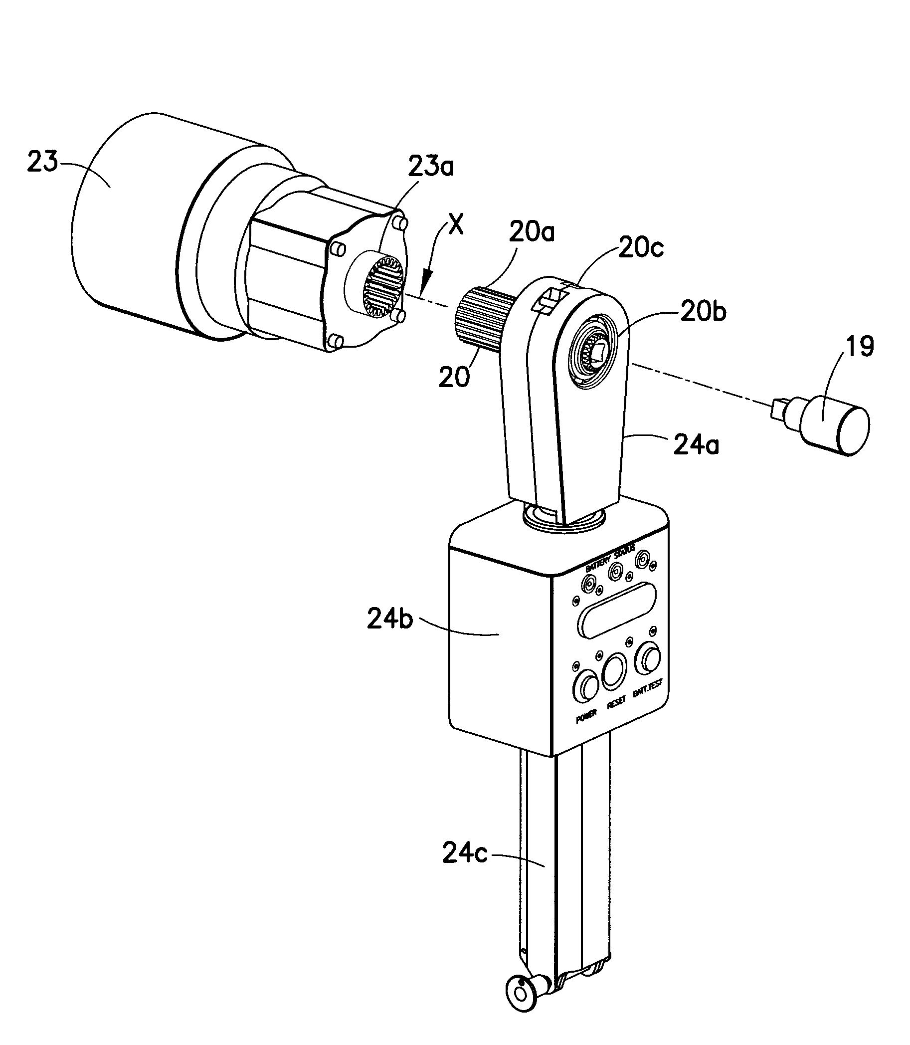
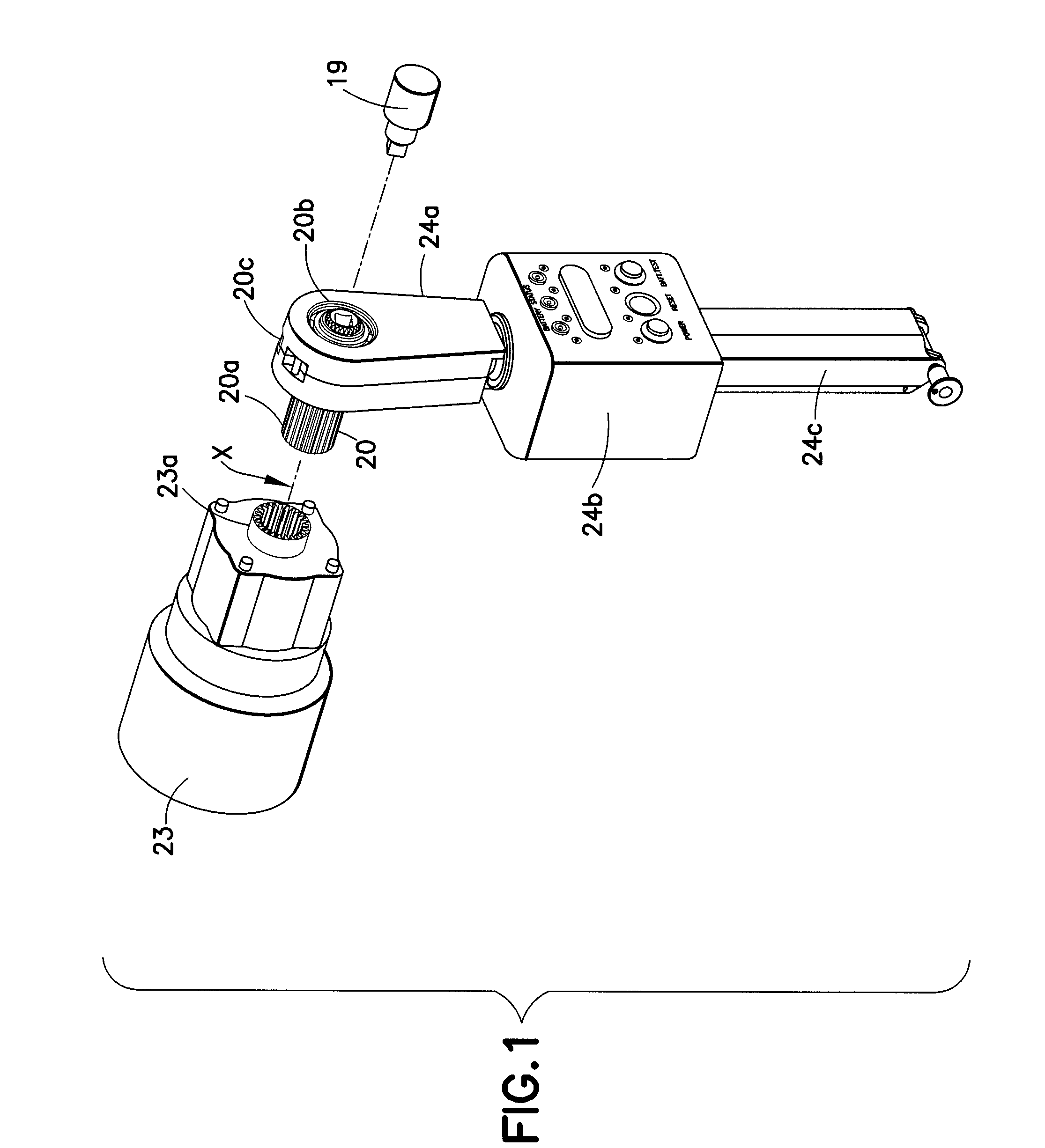
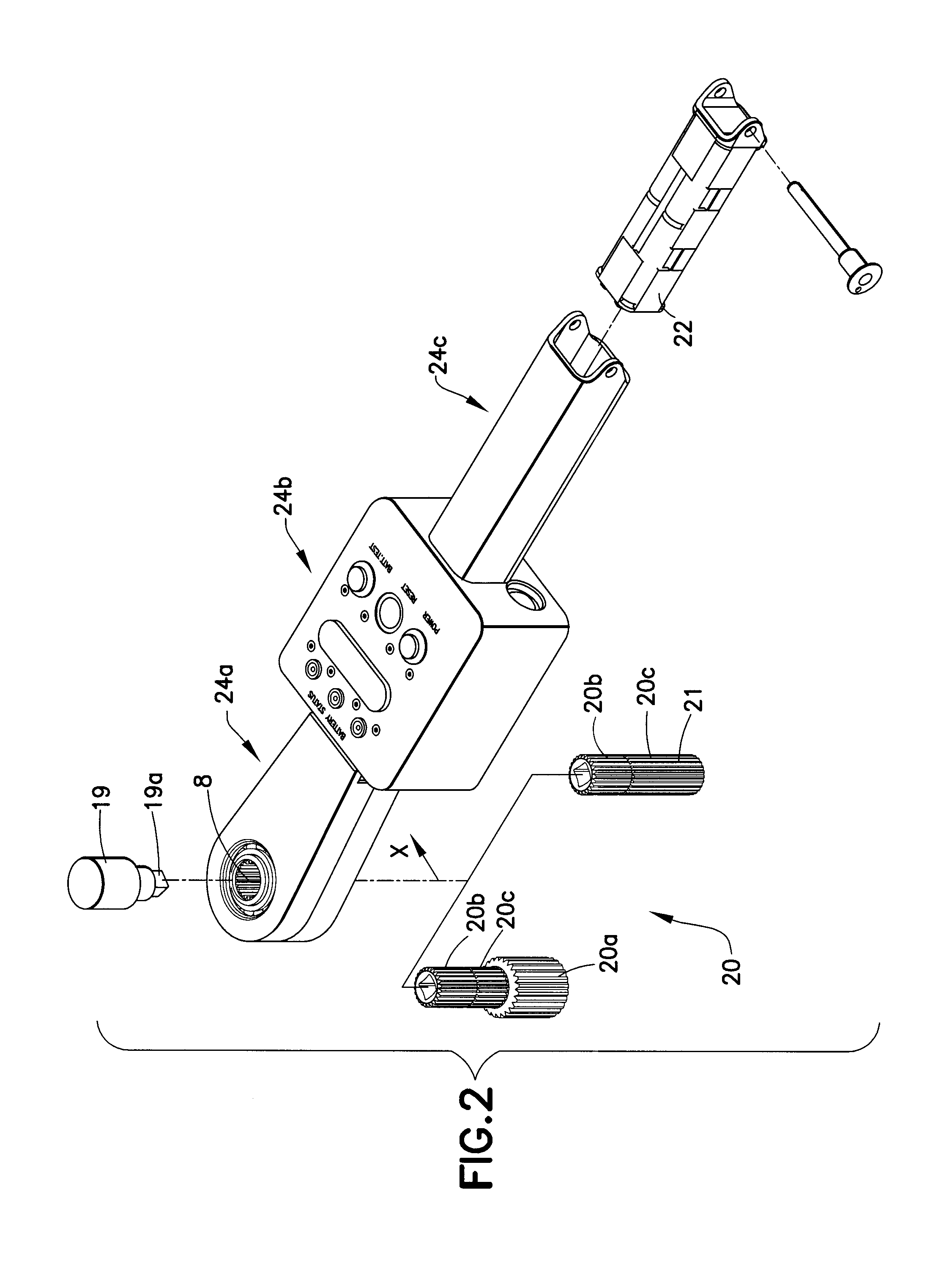
[0021]Referring to FIG. 1, a preferred embodiment of a Revolution Counter Tool is illustrated having a splined shaft 20 having an output end 20a adapted to be coupled to a driven part 23a of a power train sy...


PUM


Abstract

A preferred embodiment of a revolution counter tool and method employs an adapter shaft with input and output ends coupled in-line between a driven part and a driving part, and an intermediate portion between the input and output ends that is coupled to a rotary encoder and encoder circuit. A memory counter circuit maintains a count of turns and increments of the driven part by the driving part, and a reference setting circuit sets a reference setting of the memory counter circuit when a count is to be taken. The device body has a first portion mounting the adapter shaft with the rotary encoder, an intermediate housing containing the memory counter circuit, and a second portion at a distance from the first portion and of a sufficient mass that acts to orient the device body to a gravity-determined position as a reference position. The memory counter circuit receives output signals from the rotary encoder circuit and maintains a count relative to a reference setting using the reference position of the device body as indexed by gravity.

Description

TECHNICAL FIELD[0001]This disclosure generally relates to a tool and associated method for keeping accurate count of the number of turns (and fractional increments thereof) that a driving part such as a wrench is used to drive or turn a driven part such as a shaft or gear. In particular, it is directed to a mechanical revolution counter for keeping track of the number of turns a driven part is driven for adjustment to a target or optimal position.BACKGROUND[0002]Existing rotation counters typically have a moving part that is clamped or fixed to a rotating shaft and a stationary part that is attached to or positioned in tandem with a non-rotating structure. A rotation sensor or rotary encoder is coupled between the two parts to count the number of turns of the moving part relative to the stationary part.[0003]Some devices use a pendulum or weight to form the non-rotating part that stays in a downward position under gravity. For example, a hubometer is a well-known device that is moun...

Claims


Application Information

Patent Timeline
Patent Type & Authority Applications(United States)
IPC IPC(8): G07C9/00
CPCG01D5/3473
Inventor WHEELER, SCOTT R.BAULIER, DOMINIC
Owner THE BOEING CO
Why Eureka
Try Eureka