
Display device and driving method thereof

a technology of a display panel and a driving method, which is applied in the direction of semiconductor devices, electrical discharge tubes, instruments, etc., can solve the problems of display panel brightness uniformity deterioration, deviation of threshold voltage of tfts in the display panel,

Active Publication Date: 2010-04-01
SAMSUNG DISPLAY CO LTD +1
View PDF11 Cites 73 Cited by
  • Summary
  • Abstract
  • Description
  • Claims
  • Application Information

AI Technical Summary

Benefits of technology

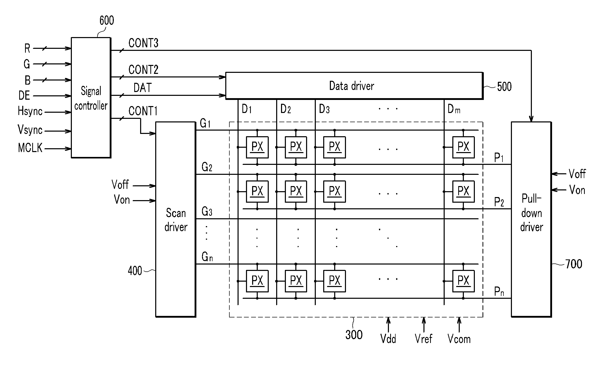
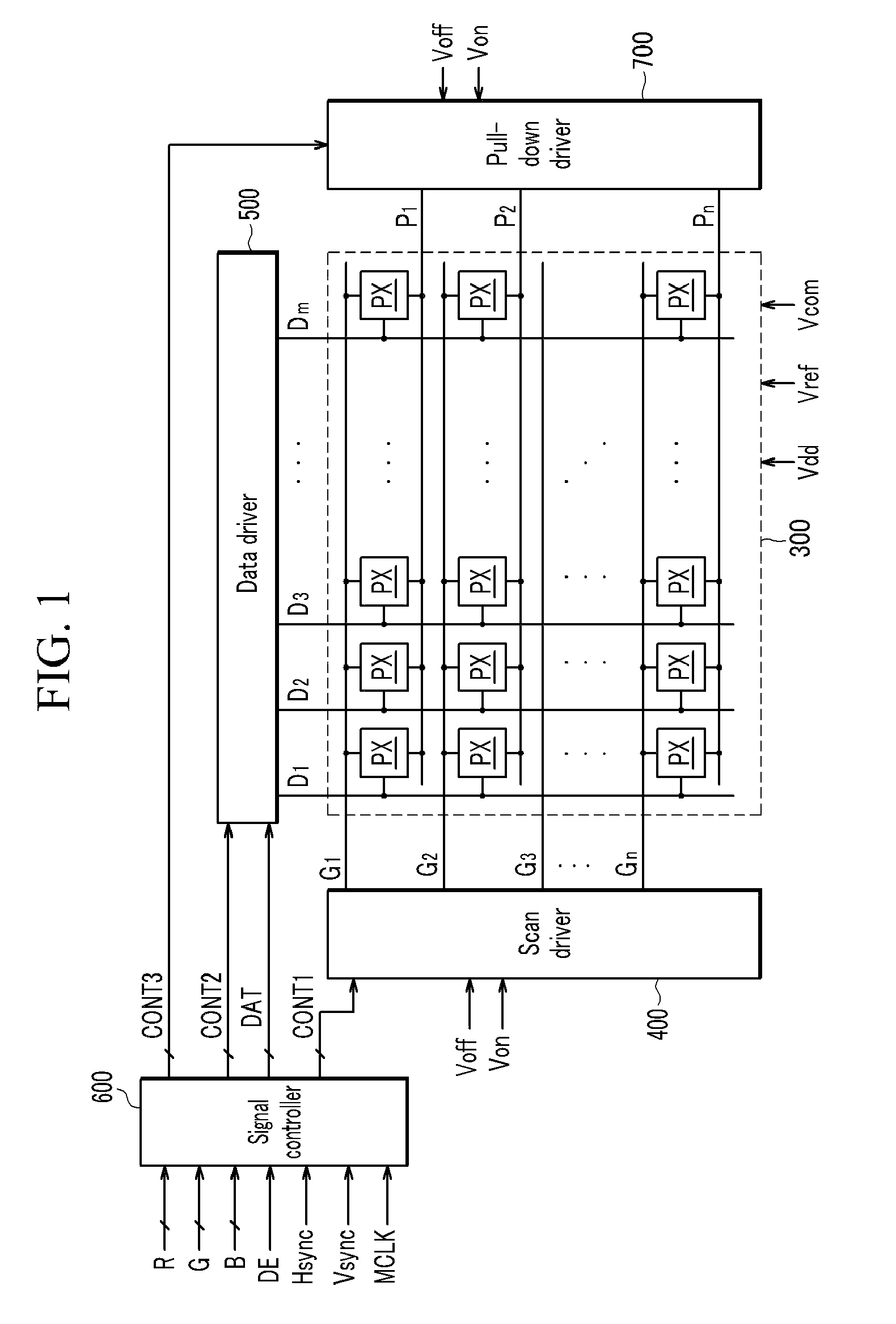
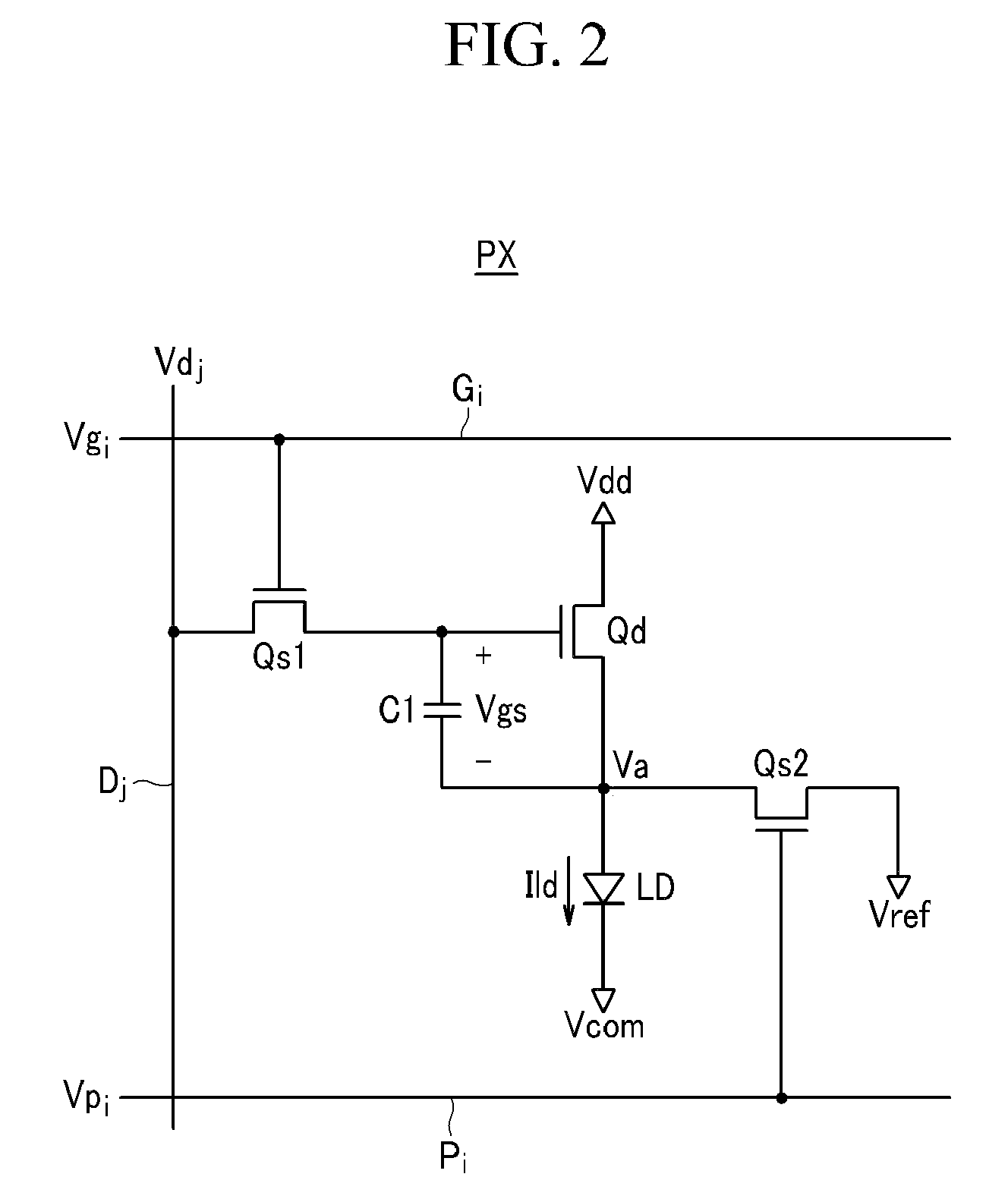
The present invention provides a display device and a driving method that can compensate for the threshold voltage of a thin film transistor. This is achieved by applying a black voltage and a gray voltage to the control terminal of the driving transistor, which results in a reference voltage based on the threshold voltage of the first transistor. The reference voltage is then used to store a control voltage for the light emitting element in a subsequent period, allowing for a more accurate and efficient display. The invention also includes a signal line, a scan line, a data line, and a capacitor for further enhancement of the display device.

Problems solved by technology

When the active layer of the TFT is formed, deviation in threshold voltages of the TFTs in a display panel may occur due to non-uniformity in a manufacturing process.
As a result, brightness uniformity of a screen may deteriorate.

Method used


Image

  • Display device and driving method thereof
  • Display device and driving method thereof
  • Display device and driving method thereof

Examples


Embodiment Construction

[0025]The invention is described more fully hereinafter with reference to the accompanying drawings, in which exemplary embodiments of the invention are shown. This invention may, however, be embodied in many different forms and should not be construed as limited to the exemplary embodiments set forth herein. Rather, these exemplary embodiments are provided so that this disclosure is thorough, and will fully convey the scope of the invention to those skilled in the art. In the drawings, the size and relative sizes of layers and regions may be exaggerated for clarity. Like reference numerals in the drawings denote like elements.

[0026]It will be understood that when an element or layer is referred to as being “on” or “connected to” another element or layer, it can be directly on or directly connected to the other element or layer, or intervening elements or layers may be present. In contrast, when an element is referred to as being “directly on” or “directly connected to” another elem...


PUM


Abstract

In a pixel of a display device, a first transistor of which an second terminal is connected to a first terminal of a light emitting element supplies a driving current that corresponds to a voltage between a control terminal and the second terminal to the light emitting element, and a second terminal of the light emitting element is connected to a driving voltage. At least one second transistor transmits a black voltage that corresponds to a black gray to the control terminal of the first transistor in a first period and a second period, and transmits a gray voltage that corresponds to an input image signal to the control terminal of the first transistor in a third period. A third transistor is connected between the first terminal of the light emitting element and a voltage supply line to transmit a reference voltage, and the third transistor is turned on in the first period and turned off in the second period. A capacitor is connected between the control terminal and the source of the first transistor, stores a control voltage based on a threshold voltage of the first transistor in the second period, and stores a voltage based on the control voltage and the gray voltage in the third period.

Description

CROSS REFERENCE TO RELATED APPLICATION[0001]This application claims priority from and the benefit of Korean Patent Application No. 10-2008-0095208, filed on Sep. 29, 2008, which is hereby incorporated by reference for all purposes as if fully set forth herein.BACKGROUND OF THE INVENTION[0002]1. Field of the Invention[0003]The present invention relates to a display device and a driving method thereof.[0004]2. Discussion of the Background[0005]Display devices may include a plurality of pixels arranged in a matrix, whereby images are displayed by controlling the optical intensity of each of the pixels on the basis of predetermined luminance information. Among display devices, an organic light emitting display displays images by electrically exciting light emitting fluorescent materials. An organic light emitting display is self-luminous, may have low power consumption, a wide viewing angle, and good response speed of a pixel, and may easily display high-quality moving pictures.[0006]Ea...

Claims


Application Information

Patent Timeline
Patent Type & Authority Applications(United States)
IPC IPC(8): G09G3/30
CPCG09G3/3233G09G2300/0819G09G2320/043G09G2310/0262G09G2300/0842H01J37/2955H01L21/02576H01L29/742
Inventor LEE, BAEK-WOONKWON, OH-KYONG
Owner SAMSUNG DISPLAY CO LTD
Learn More