Optical apparatus

a technology of optical equipment and lens, applied in the field of optical equipment, can solve the problems of unstable tilt of the lens with respect to the optical axis, low optical axis accuracy, and inability to perform high-speed lens driving, and achieve the effect of stably realizing high-speed lens driving

Inactive Publication Date: 2010-04-01
CANON KK
View PDF16 Cites 51 Cited by
  • Summary
  • Abstract
  • Description
  • Claims
  • Application Information

AI Technical Summary

Benefits of technology

[0010]The present invention provides an optical apparatus capable of stably realizing a high-speed lens drive.

Problems solved by technology

However, in such a structure, due to a sliding friction on the guide axis, a high-speed lens driving can not be performed.
Further, there is a problem that a sliding noise is generated by the sliding friction, or the like.
However, since the lens of this optical apparatus is floated and supported by an electromagnetic force, the tilt of the lens with respect to an optical axis is unstable at a lens position other than a position where a coil finally contacts a magnet in an optical axis direction.
Further, there is a possibility that the lens is tilted by a behavior of the lens during a focusing operation.
In this case, because the lens vibrates with high speed, the lens is easily tilted in accordance with the vibration mode and there is a possibility that a false image evaluation may be performed.

Method used


Image

  • Optical apparatus
  • Optical apparatus
  • Optical apparatus

Examples


embodiment 1

[0040]First, embodiment 1 of the present invention will be described.

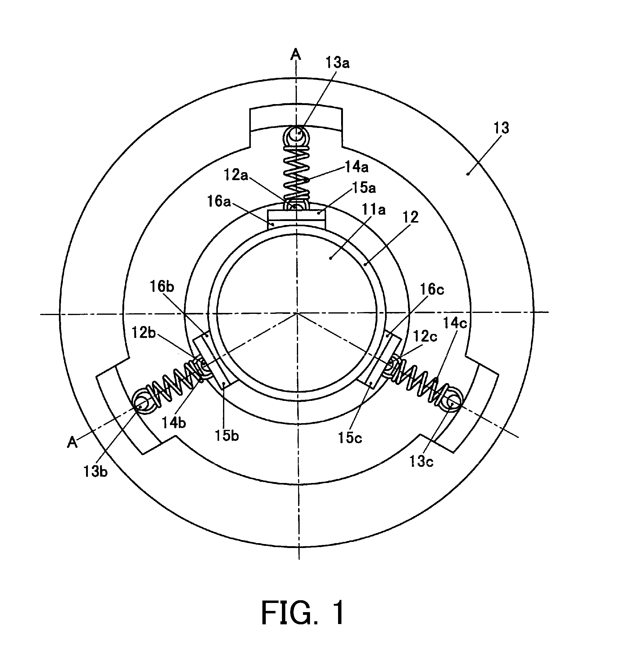
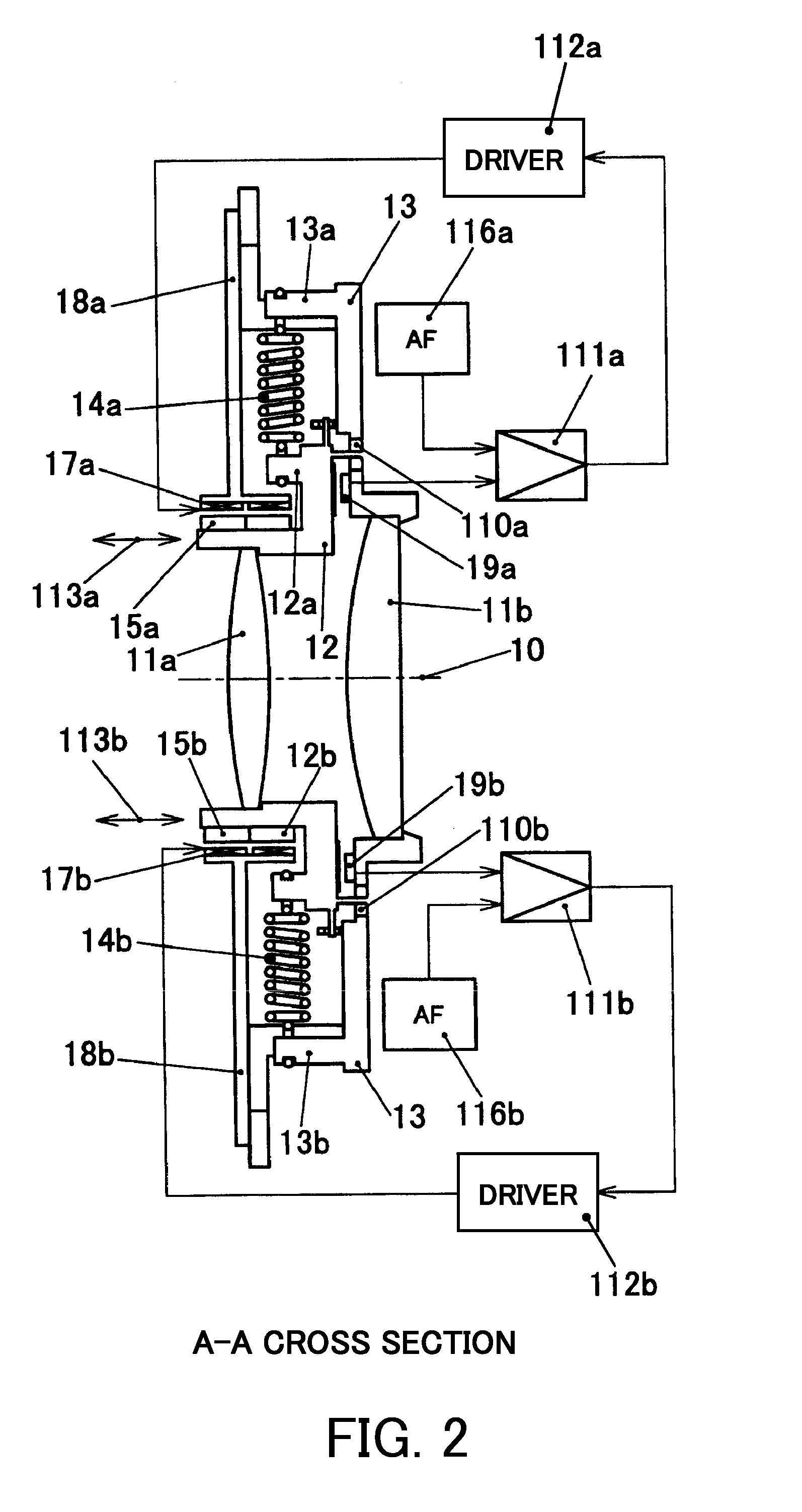
[0041]FIG. 1 is a plan view of an optical apparatus in the present embodiment. FIG. 2 is a cross-sectional view of A-A section in FIG. 1.

[0042]In FIG. 1, coils 17a to 17c and coil holders 18a to 18c described later are omitted. FIG. 3 is an elevation view showing the optical apparatus of the present embodiment, including the coils 17a to 17c and the coil holders 18a to 18c.

[0043]In FIGS. 1 to 3, reference numeral 11a denotes a focus correction lens which is provided on a lens frame 12 that is a moving frame. Reference numeral 11b denotes a fixed lens which is provided on a supporting portion 13 (a fixed portion). As shown in FIG. 2, the focus correction lens 11a and the fixed lens 11b are arranged in a direction of an optical axis 10 that is an imaging optical axis. The lens frame 12 holds the focus correction lens 11a and is configured to be movable in the imaging optical axis direction (optical axis direction).

[...

embodiment 2

[0115]Next, embodiment 2 of the present invention will be described. In the present embodiment, the same descriptions as those of embodiment 1 will be omitted.

[0116]FIG. 15 is a plan view of an optical apparatus in the present embodiment. FIG. 16 is a cross-sectional view of A-A section of FIG. 15 in the optical apparatus of the present embodiment. Embodiment 2 is different from embodiment 1 in that the lens frame 12 is not only driven in an optical axis direction (a direction indicated by arrows 113a and 113b), but also driven in a direction orthogonal to the optical axis direction (a direction indicated by arrows 1506a and 1506b).

[0117]As shown in FIGS. 15 and 16, the supporting portion 13 (fixed portion) is provided with shake correcting coils 1502a and 1502b along lines 1501a and 1501b tilted at 45 degrees with respect to an upward and downward direction on a paper surface. The shake correcting permanent magnets 1503a and 1503b are provided on a fixed portion 1510 inside the len...

embodiment 3

[0149]Next, embodiment 3 of the present invention will be described. In the present embodiment, the same descriptions as those of embodiment 1 and 2 will be omitted.

[0150]FIG. 20 is a plan view of an optical apparatus of the present embodiment. FIG. 21 is a cross-sectional view of A-A section in FIG. 20. The optical apparatus of the present embodiment is different from that of embodiment 1 in that the lens frame 12 is not only driven in an optical axis direction (a direction indicated by arrows 113a and 113b) but also driven in a direction orthogonal to the optical axis direction (directions indicated by arrows 1506a and 1506b). Further, the present embodiment is different from embodiment 2 in that the lens frame 12 of the present embodiment is driven in the direction orthogonal to the optical axis while the supporting portion 13 of embodiment 2 is driven in the direction orthogonal to the optical axis.

[0151]As shown in FIGS. 20 and 21, the lens frame 12 is provided with the shake c...


PUM


Abstract

An optical apparatus includes a lens frame 12 which holds a focus correction lens 11a and is movable in an optical axis direction, optical axis direction position detectors 19a to 19c which are arranged on one of the lens frame 12 and a supporting portion 13 inside a barrel and detect signals in accordance with a distance to the other one, driving portions 112a to 112c and coils 17a to 17c (driver) which drive the lens frame 12 in the optical axis direction, an optical axis direction movement limiting member of the lens frame, and a lens CPU 1204 (controller) which controls the driver so as to suppress a tilt of the focus correction lens 11a based on a signal detected by the optical axis direction position detectors 19a to 19c whose sensitivities have been calibrated in association with the driving portions and the optical axis direction movement limiting member.

Description

BACKGROUND OF THE INVENTION[0001]1. Field of the Invention[0002]The present invention relates to an optical apparatus, and more particularly to an optical apparatus capable of stably performing a high-speed lens drive.[0003]2. Description of the Related Art[0004]As a technology of moving a lens with high speed and low noise to perform a focusing, as disclosed in Japanese Patent Laid-open No. 5-066336, a technology where a permanent magnet is arranged at a lens side and a coil is arranged at a fixed portion side to drive the lens by direct driving has been known. In this technology, the lens is guided by a guide axis along an optical axis and a lens frame slides on the guide axis to perform lens driving in an optical axis direction.[0005]However, in such a structure, due to a sliding friction on the guide axis, a high-speed lens driving can not be performed. Further, there is a problem that a sliding noise is generated by the sliding friction, or the like.[0006]As a lens driving meth...

Claims


Application Information

Patent Timeline
Patent Type & Authority Applications(United States)
IPC IPC(8): H04N5/228H04N5/225G02B27/64
CPCG02B7/08G02B27/646H04N5/2254H04N5/23287H04N5/23248H04N5/23258H04N5/23212H04N23/55H04N23/673H04N23/68H04N23/6812H04N23/687
Inventor WASHISU, KOICHI
Owner CANON KK
Why Eureka
Try Eureka