QKD transmitter and transmission method

Active Publication Date: 2010-04-01
HEWLETT-PACKARD ENTERPRISE DEV LP
View PDF5 Cites 24 Cited by
  • Summary
  • Abstract
  • Description
  • Claims
  • Application Information

AI Technical Summary

Benefits of technology

[0026]Use of a retro-reflector and a modulator for modulating the retro-reflected beam effectively ensures automatic directional alignment of the transmitted QKD signal (the polarization-modulated retro-reflected photon beam) with a QKD receiver assuming the source of the photon beam is at the QKD receiver.
[0034]limiting reflection back out of the photon beam to a succession of discrete time slots,the method further comprising attenuating the photon beam in dependence on retro-reflected photon intensity such as stabilize the average retro-reflected photon count per time slot.

Problems solved by technology

However, use of a the retro-reflector exposes the QKD transmitter to an active monitoring threat by a probe beam aimed at the transmitter as the reflected probe beam will betray the polarizations carried by the QKD signal; the provision of the intensity detector permits the use of any such probe beam to be countered.

Method used


Image

  • QKD transmitter and transmission method
  • QKD transmitter and transmission method
  • QKD transmitter and transmission method

Examples


Embodiment Construction

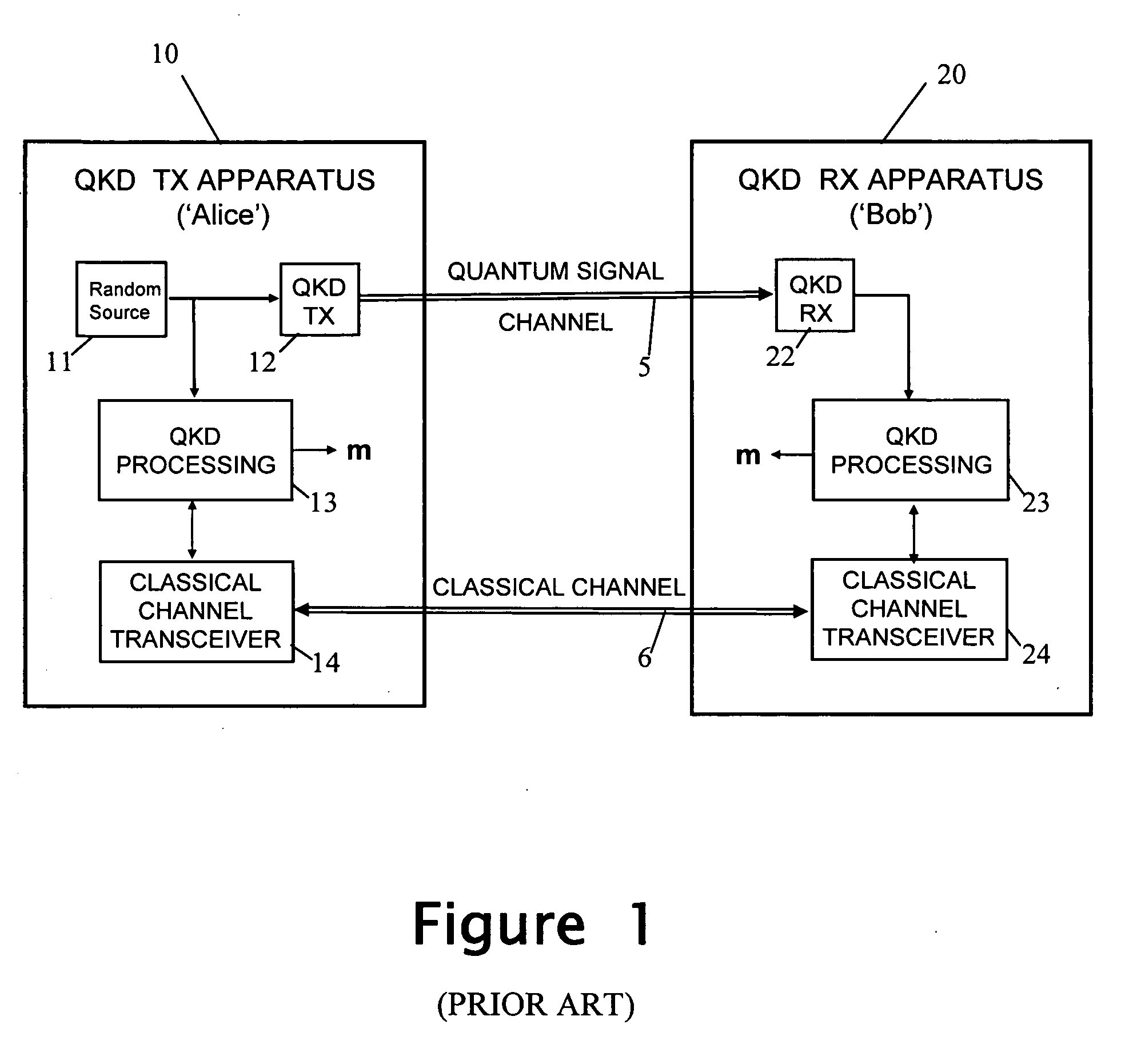
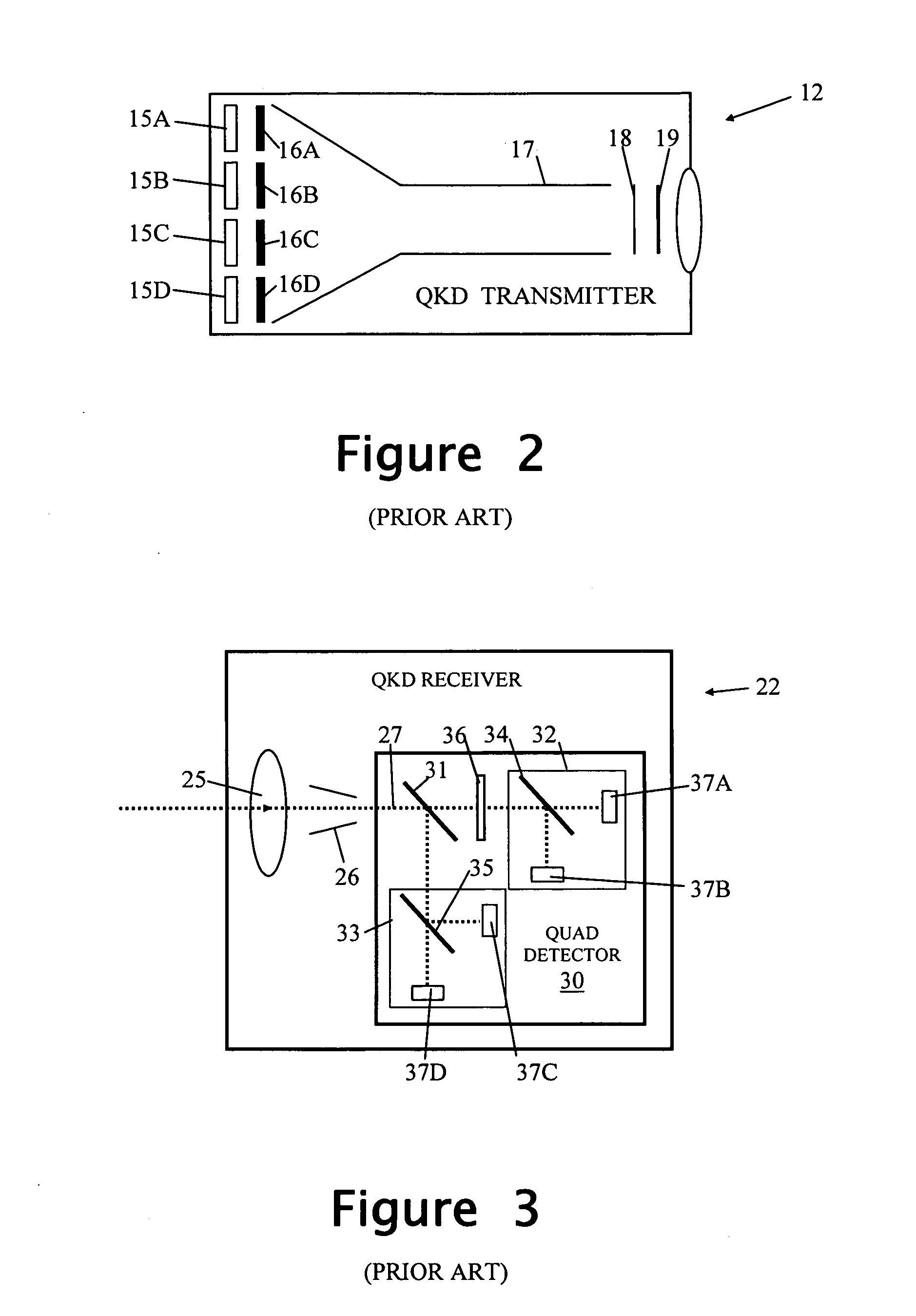
[0042]An example QKD transmitter embodying the embodiment will now be described with reference to FIGS. 5 and 6. FIG. 5 depicts both a QKD transmitter 12 of a hand-held QKD transmitting device 10 (“Alice”), and a QKD receiver 22 of QKD receiving apparatus 20 (“Bob”). The other elements of Alice and Bob (corresponding to elements 11, 13, 14, 23&24 of FIG. 1) are not illustrated as they are not directly relevant to the present invention.

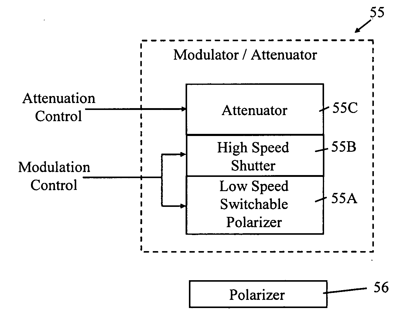
[0043]In general terms, the QKD receiving apparatus 20 (“Bob”) generates a beam of photons (“system beam”51F) which it emits in the direction of the QKD transmitting apparatus 10 (“Alice”). The system beam 51F is retro-reflected, polarization modulated and attenuated by Alice to return a small number of the original photons back to Bob (“quantum signal”51R) with random polarizations as set by Alice. The polarizations of the quantum-signal photons are then randomly detected by Bob.

[0044]In more detail, the QKD receiving apparatus 20 includes an intense ...


PUM


Abstract

In order to facilitate alignment of a QKD transmitter and QKD receiver, the transmitter is provided with a retro-reflector for returning to the receiver a photon beam originating at the latter. The transmitter is arranged to polarization modulate the retro-reflected beam. The transmitter is provided both with an intensity detector for generating an indication of retro-reflected photon intensity, and an intensity-dependent controller for controlling the QKD transmitter in dependence on the detected photon intensity. In one embodiment, this control involves aborting operation of the QKD transmitter upon an unexpectedly high photon intensity being detected; in another embodiment, the intensity indication is used to control the attenuation of the retro-reflected beam so as stabilize the average retro-reflected photon count per unit time.

Description

FIELD OF THE INVENTION[0001]The present invention relates to a QKD (Quantum Key Distribution) transmitter and transmission method suitable for use in a hand-held device.BACKGROUND OF THE INVENTION[0002]QKD methods and systems have been developed which enable two parties to share random data in a way that has a very high probability of detecting any eavesdroppers. This means that if no eavesdroppers are detected, the parties can have a high degree of confidence that the shared random data is secret. QKD methods and systems are described, for example, in U.S. Pat. No. 5,515,438, U.S. Pat. No. 5,999,285 and GB 2427317 A. Whatever particular QKD system is used, QKD methods typically involve QKD transmitting apparatus 10 (see FIG. 1 of the accompanying drawings) using a QKD transmitter 12 to send a random data set provided by random source 11, over a quantum signal channel 5 to a QKD receiver 22 of QKD receiving apparatus 20. The QKD transmitting and receiving apparatus 10, 20 then respe...

Claims


Application Information

Patent Timeline
Patent Type & Authority Applications(United States)
IPC IPC(8): H04L9/08H04B10/04H04L9/00
CPCH04B10/114H04L9/0858H04B10/70
Inventor HARRISON, KEITHMUNRO, WILLIAMSPILLER, TIMOTHYTAN, MICHAELDULIGALL, JOANNAIONICIOIU, RADU
Owner HEWLETT-PACKARD ENTERPRISE DEV LP
Why Eureka
Try Eureka