
Method and graphical user interface for modifying depth maps

a technology of depth information and graphical user interface, which is applied in the field of methods and systems for generating depth information, can solve the problems of high hardware and/or cumbersome recording procedures, difficult to accurately obtain accurate depth maps, and difficult to achieve accurate depth maps

Inactive Publication Date: 2010-04-01
HER MAJESTY THE QUEEN & RIGHT OF CANADA REPRESENTED BY THE MIN OF IND THROUGH THE COMM RES CENT
View PDF21 Cites 209 Cited by
  • Summary
  • Abstract
  • Description
  • Claims
  • Application Information

AI Technical Summary

Benefits of technology

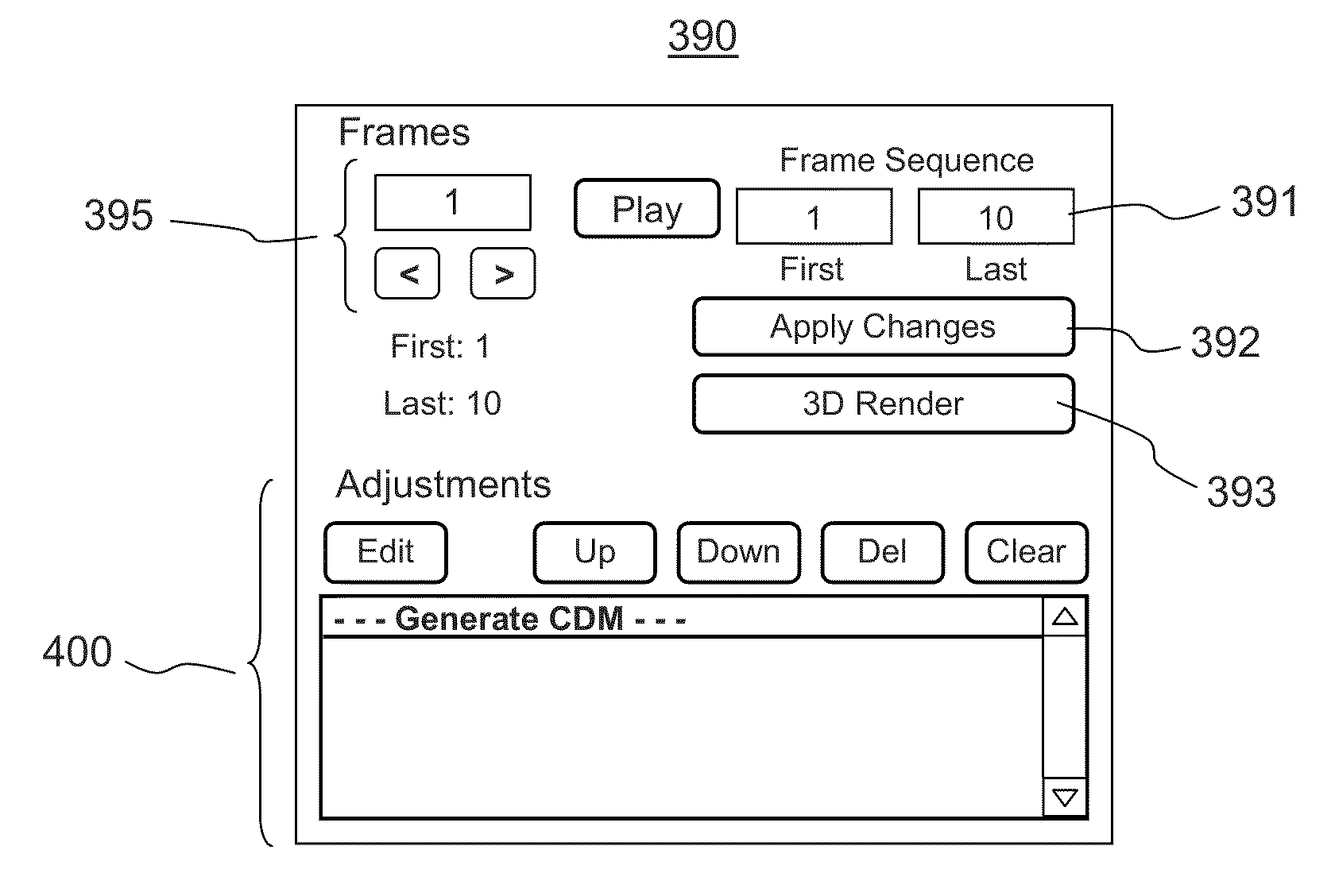
[0020]One feature of the present invention provides a graphical user interface (GUI) for modifying depth maps of color images or sequences of color images, which provides GUI tools for displaying the first color image, the region visualization image, the depth map, and the modified depth map on the computer screen, and for receiving the first and second user inputs, and for saving the pixel selection rule and the selected depth modification rule obtained using the first color image for use in modifying depth maps of other color images.

Problems solved by technology

One problem with conventional DIBR is that accurate depth maps are expensive or cumbersome to acquire either directly or from a 2D image.
Disadvantageously, these methods require highly specialized hardware and / or cumbersome recording procedures, restrictive scene lighting and limited scene depth.
Although many algorithms exist in the art for generating a depth map from a 2D image, they are typically computationally complex and often require manual or semi-automatic processing.
A specially designed computer software may then be used to track the regions in consecutive frames to allocate the depth values according to the markings This type of approach requires trained technicians, and the task can be quite laborious and time-consuming for a full-length movie.
However, extracting depth from blur may be a difficult and / or unreliable task, as the blur found in images can also arise from other factors, such as lens aberration, atmospheric interference, fuzzy objects, and motion.
In addition, a substantially same degree of blur arises for objects that are farther away and that are closer to the camera than the focal plane of the camera.
Although methods to overcome some of these problems and to arrive at more accurate and precise depth values have been disclosed in the art, they typically require more than one exposure to obtain two or more images.
A further disadvantage of this approach is that it does not provide a simple way to determine depth values for regions for which there is no edge or texture information and where therefore no blur can be detected.
Generally, regardless of the method used, depth maps generated from 2D images can contain objects and / or regions with inaccurate depth information.
Although this can be corrected by a user through the use of a photo editing software by identifying and selecting object / regions in the image and then changing the depth contained therein, this task can be tedious and time-consuming especially when this has to be done for images in which there are many different minute objects or textures.
Furthermore, even though commercially available software applications for generating depth maps from standard 2D images can be used for editing of depth maps, they typically involve complex computations and require long computational time.
For example, one commercial software allows for manual seeding of a depth value within an object of an image, followed by automatic expansion of the area of coverage by the software to cover the region considered to be within an “object,” such as the trunk of a tree or the sky; however, where and when to stop the region-growing is a computationally challenging task.
Furthermore, for video clips the software has to track objects over consecutive frames and this requires further complex computations.
Being able to do that manually for one image frame and then automatically repeat the process for other image frames with similar contents is a challenge.

Method used


Image

  • Method and graphical user interface for modifying depth maps
  • Method and graphical user interface for modifying depth maps
  • Method and graphical user interface for modifying depth maps

Examples


Embodiment Construction

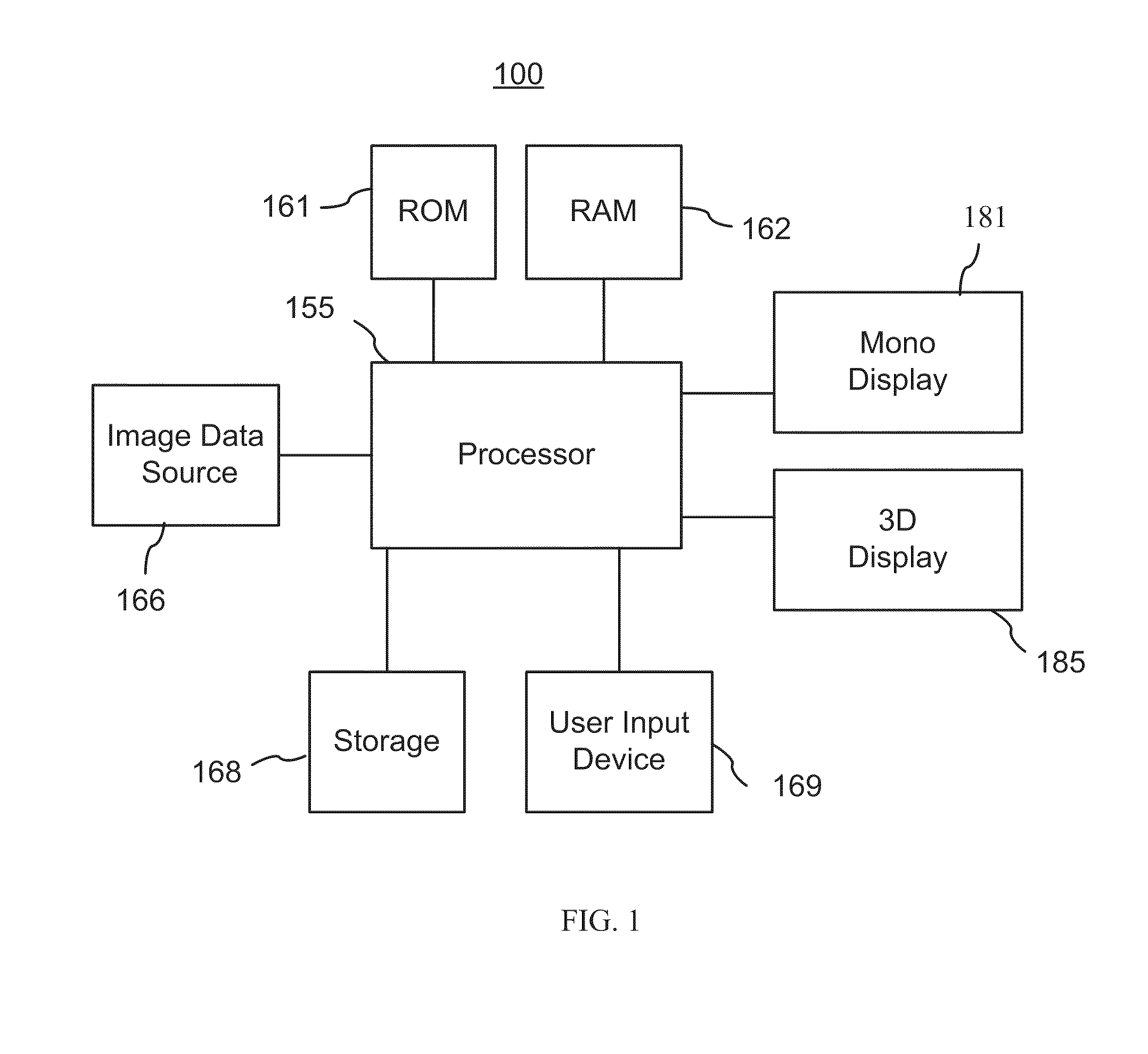
[0032]The invention will be described in connection with a number of exemplary embodiments. To facilitate an understanding of the invention, many aspects of the invention are described in terms of sequences of actions to be performed by functional elements of a video-processing system. It will be recognized that in each of the embodiments, the various actions including those depicted as blocks in flow-chart illustrations and block schemes could be performed by specialized circuits, for example discrete logic gates interconnected to perform a specialized function, by computer program instructions being executed by one or more processors, or by a combination of both. Moreover, the invention can additionally be considered to be embodied entirely within any form of a computer readable storage medium having stored therein an appropriate set of computer instructions that would cause a processor to carry out the techniques described herein. Thus, the various aspects of the invention may be...


PUM


Abstract

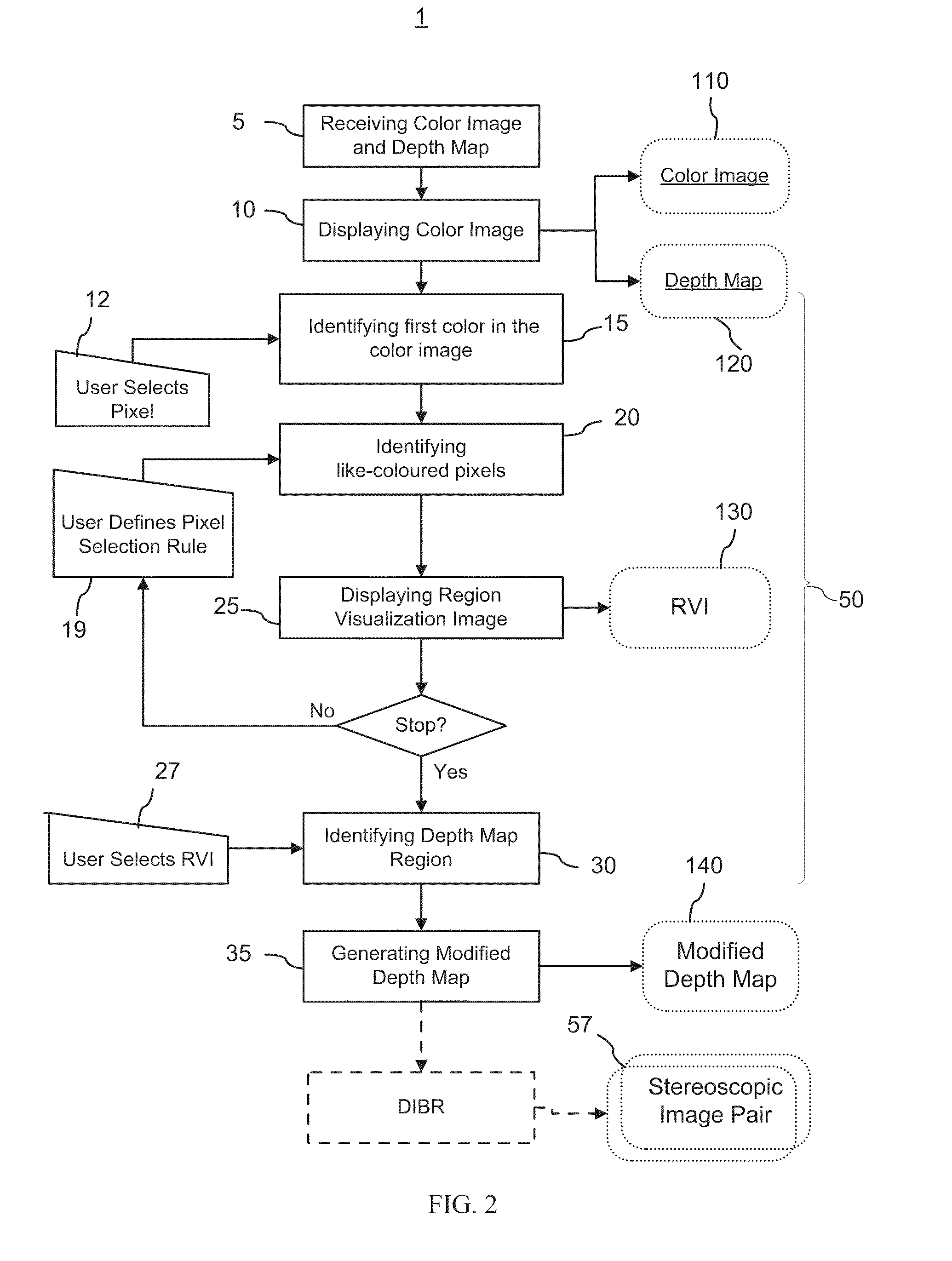
The invention relates to a method and a graphical user interface for modifying a depth map for a digital monoscopic color image. The method includes interactively selecting a region of the depth map based on color of a target region in the color image, and modifying depth values in the thereby selected region of the depth map using a depth modification rule. The color-based pixel selection rules for the depth map and the depth modification rule selected based on one color image from a video sequence may be saved and applied to automatically modify depths maps of other color images from the same sequence.

Description

CROSS-REFERENCE TO RELATED APPLICATIONS[0001]The present invention claims priority from U.S. Provisional Patent Application No. 61 / 129,869 filed Jul. 25, 2008, entitled “Method and Graphical User Interface for Modifying Depth Maps”, which is incorporated herein by reference, and is a continuation in part of a U.S. patent application Ser. No. 12 / 060,978, filed Apr. 2, 2008, entitled “Generation Of A Depth Map From A Monoscopic Color Image For Rendering Stereoscopic Still And Video Images”, which claims priority from U.S. Provisional Patent Application No. 60 / 907,475 filed Apr. 3, 2007, entitled “Methods for Generating Synthetic Depth Maps from Colour Images for Stereoscopic and Multiview Imaging and Display”, which are incorporated herein by reference for all purposes.TECHNICAL FIELD[0002]The present invention generally relates to methods and systems for generating depth information for monoscopic two-dimensional color images, and more particularly relates to a computer implanted met...

Claims


Application Information

Patent Timeline
Patent Type & Authority Applications(United States)
IPC IPC(8): G06K9/00G06T15/00G06F3/048
CPCG06T7/0051H04N13/026H04N13/0257G06T2207/20092G06T7/50H04N13/257H04N13/261
Inventor TAM, WA JAMESVAZQUEZ, CARLOS
Owner HER MAJESTY THE QUEEN & RIGHT OF CANADA REPRESENTED BY THE MIN OF IND THROUGH THE COMM RES CENT
Learn More