Prismatic secondary battery and battery module thereof

Inactive Publication Date: 2010-04-01
SANYO ELECTRIC CO LTD
View PDF4 Cites 114 Cited by
  • Summary
  • Abstract
  • Description
  • Claims
  • Application Information

AI Technical Summary

Benefits of technology

[0032]With the battery module according to the second aspect of the invention, any number of the prismatic secondary batteries can be connected into a module in a low-cost and simple manner without a mistake in polarity by processing the insulating materials, while not using the special spacers as additional parts, as are used in the related art. In addition, because the certain predetermined gaps are provided between the adjacent batteries connected to each other, it is possible to radiate the heat generated from each of the prismatic secondary batteries when using or charging the batteries, thus enabling the batteries to be charged or discharged at a des

Problems solved by technology

Therefore, there are potential problems caused by a harmful effect on the connection of the axis of the terminal 109 to the collector, such as a poor connection or increase in internal resistance due to the poor connection, or, furthermore, a poor seal between the terminal and the sealing plate 100B resulting in an outward leakage of electrolyte.
In addition, although the individual batteries of this battery module 100 are connected in series, desired output is not obtained if the batteries are connected with a wrong polarity.
However, even using such a method, erroneous connections can occur due to carelessness of workers and so on.
On the other hand, according to the battery module of JP-A-2005-322647 described above, the swinging movement suffered by the related art described above is not likely to occur be

Method used


Image

  • Prismatic secondary battery and battery module thereof
  • Prismatic secondary battery and battery module thereof
  • Prismatic secondary battery and battery module thereof

Examples


Embodiment Construction

[0041]An exemplary embodiment of the invention will now be described with reference to the accompanying drawings. However, it should be understood that the embodiment below is intended by way of illustrative examples of a prismatic secondary battery and a battery module using these prismatic secondary batteries that carry out the technical concepts of the invention, and is not intended by way of limiting the invention to these particular examples. The invention could equally well be applied to yield other embodiments within the scope and spirit of the claims.

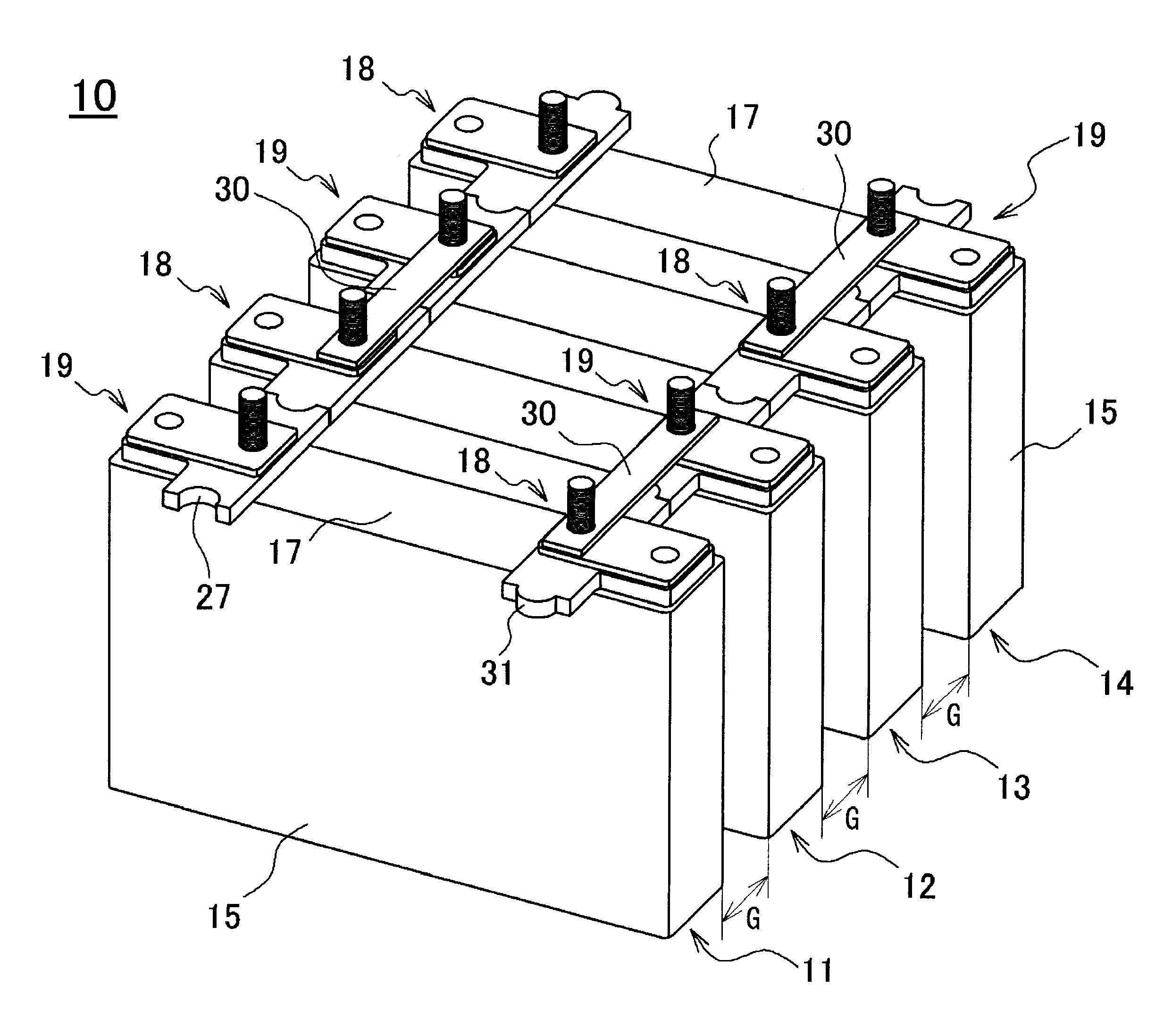
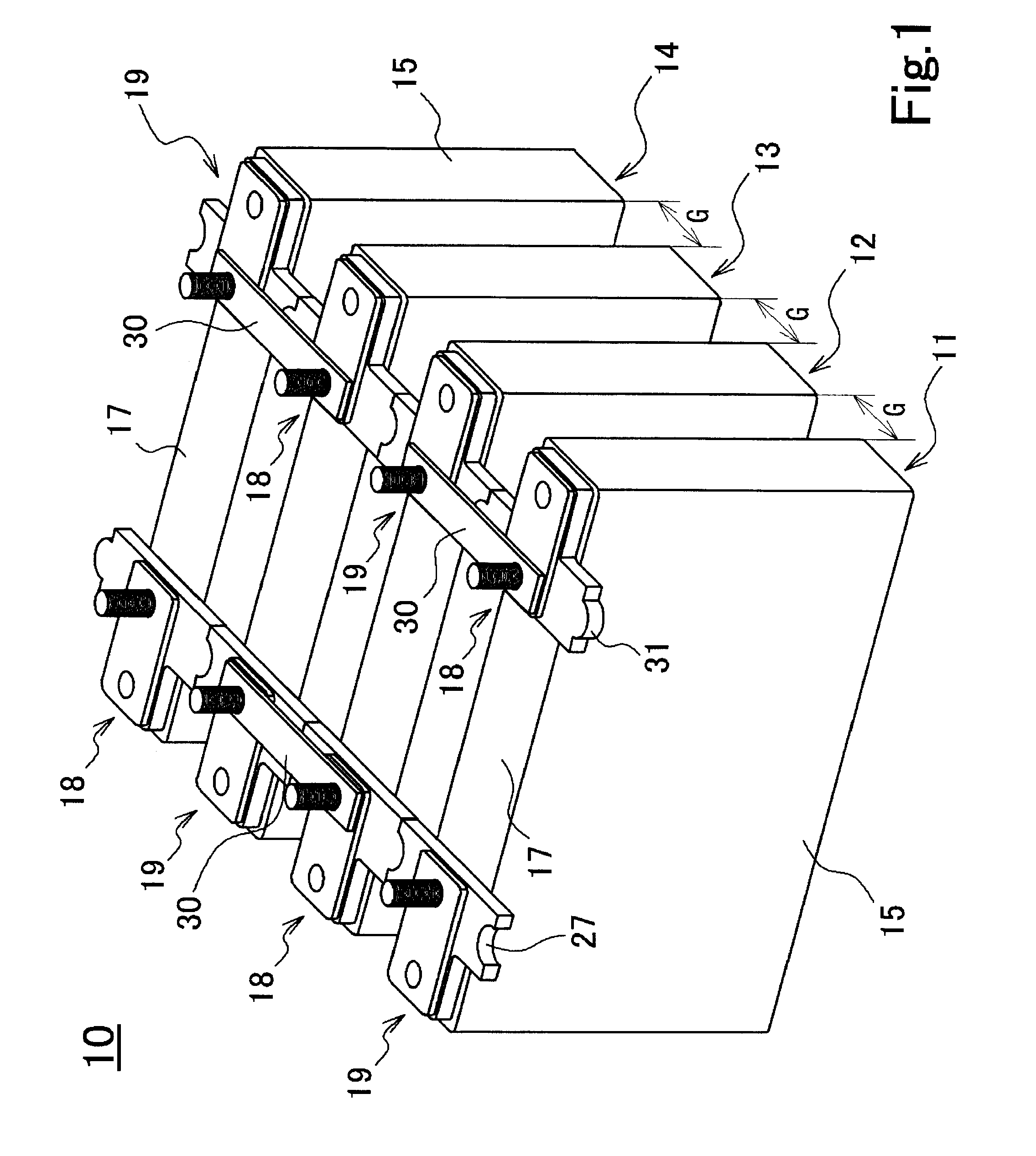
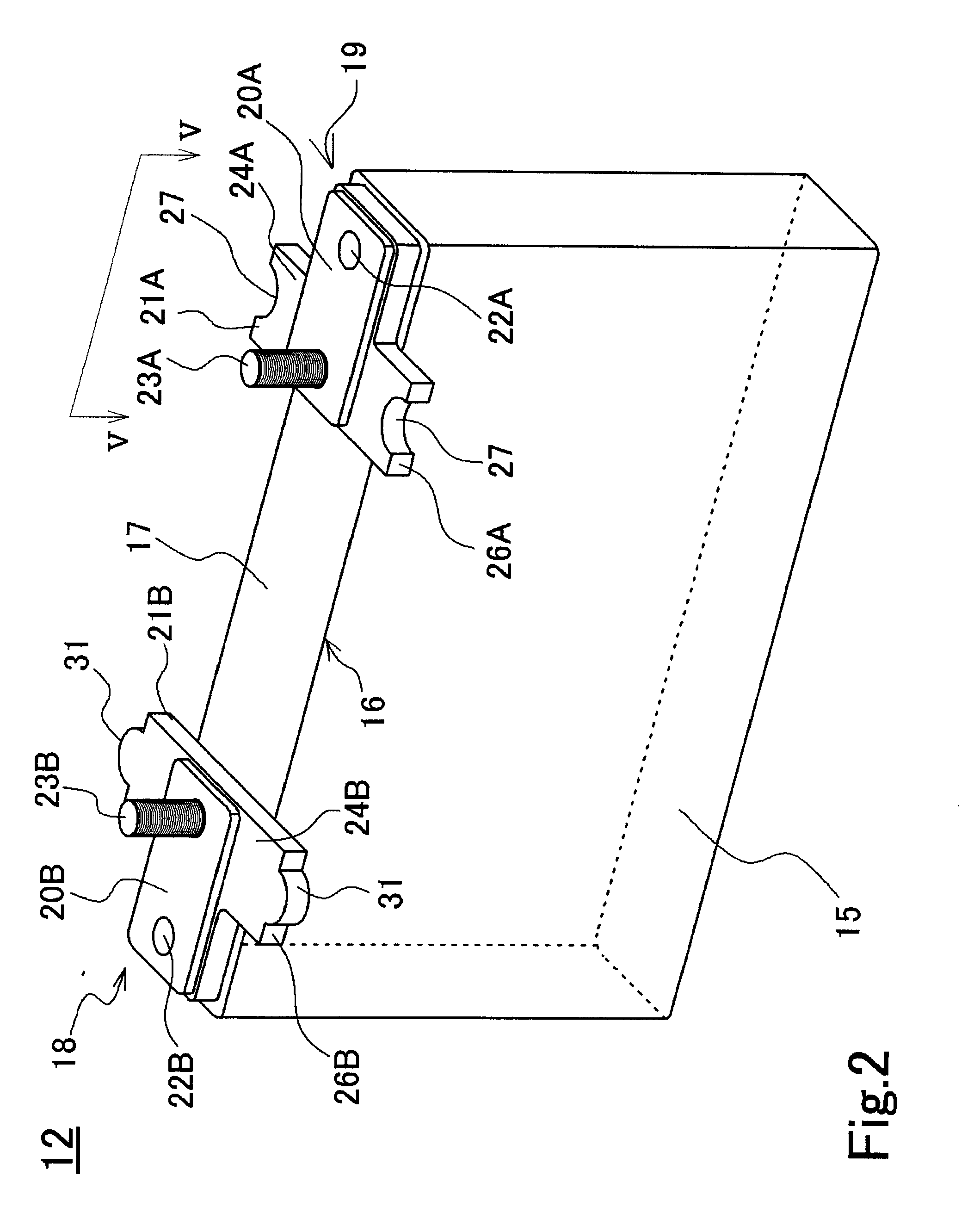
[0042]FIG. 1 is an external perspective view of a battery module formed by connecting a plurality of prismatic secondary batteries according to the exemplary embodiment. FIG. 2 is an external perspective view of one of the prismatic secondary batteries constituting the battery module of FIG. 1. FIG. 3A is a plan view of a terminal plate of a negative electrode terminal; FIG. 3B is a cross-sectional view along line IIIB-IIIB in F...


PUM


Abstract

A negative electrode terminal 19 and a positive electrode terminal 18 of a prismatic secondary battery 12 of the present invention are provided with terminal plates 20A and 20B, respectively, that are electrically connected to a negative electrode plate and a positive electrode plate, respectively, and with insulating materials 21A and 21B, respectively, that electrically insulate the terminal plates 20A and 20B, respectively, from a sealing plate 17. The insulating materials 21A and 21B are provided with connecting portions 24A and 24B, respectively, that are formed with connection contact portions composed of recessed portions 27 and protruding portions 31, respectively, having shapes complementary with each other. According to the prismatic battery 12 of the invention, any number of the batteries can easily be connected without a mistake in polarity to obtain a modularized battery.

Description

TECHNICAL FIELD[0001]The present invention relates to a prismatic secondary battery and to a battery module using a plurality of these batteries. In more detail, the invention relates to a prismatic secondary battery, a plurality of which can easily be connected without a mistake in polarity when being modularized, and to a battery module using the plurality of prismatic secondary batteries.BACKGROUND ART[0002]An individual battery has a low electromotive force. Even a lithium ion battery that is said to have a relatively high electromotive force has an electromotive force of as low as approximately 4 volts. In the case of using the battery for high-power applications such as an electric vehicle, so-called modularization is used in which a plurality of batteries are connected in series. This modularization is achieved, for example, by using a method in which a positive electrode terminal and a negative electrode terminal of each battery are extended, then these extended terminals ar...

Claims


Application Information

Patent Timeline
IPC IPC(8): H01M10/04H01M2/30H01M50/528H01M50/176H01M50/209H01M50/507H01M50/517
CPCH01M2/0217H01M2/06H01M2/1077Y02T10/7011H01M2/307H01M10/052H01M2/202Y02E60/10H01M50/103H01M50/561Y02P70/50H01M50/517H01M50/507H01M50/176H01M50/209
Inventor NANSAKA, KENJIYAMAUCHI, YASUHIRO
Owner SANYO ELECTRIC CO LTD
Why Eureka
Try Eureka