Skin level device for use with gastrostomy tube

Inactive Publication Date: 2010-04-01
TYCO HEALTHCARE GRP LP
View PDF18 Cites 38 Cited by
  • Summary
  • Abstract
  • Description
  • Claims
  • Application Information

AI Technical Summary

Benefits of technology

[0008]In another aspect, a gastrostomy tube comprises a body having a hub portion and a tubular portion extending distally from the hub portion. The hub portion includes a top surface and a bottom surface. The body defines a primary lumen having a first end in communication with an opening in the hub portion. The primary lumen extends through the body and has a second end in communication with an opening located in a distal end of the tubular portion. The gastrostomy tube further comprises a plurality of valves supported on the body. Each of the plurality of valves communicates with a respective secondary lumen and is adapted to engage an end of a luer tip syringe configured for injecting fluid into the gastrostomy tube. In addition, the gastrostomy tube includes an inflatable external balloon located at a proximal end of the body. The external balloon is positioned in use to engage an outer abdominal wall of a patient. Further, the gastrostomy tube comprises an inflatable internal balloon located distally from the external balloon and positioned on the tubular portion to engage an interior wall of a stomach of the patient in use. Each of the internal and external balloons is in fluid communication with at least one of the plurality of valves via one of their respective secondary lumens such that each of the external and internal balloons is inflatable from a deflated condition to an inflated condition. The external balloon can be deflated while the internal balloon is inflated to facilitate cleaning of an area adjacent a stoma site of the patient.
[0009]In yet another aspect, a gastrostomy tube comprises a body having a hub portion and a tubular portion extending distally from the hub portion. The hub portion includes a top surface and a bottom surface. The body defines a primary lumen having a first end in communication with an opening in the hub portion. The primary lumen extends through the body and has a second end in communication with an opening located in a distal end of the tubular portion. The gastrostomy tube also includes a port supported on the body. The port communicates with a secondary lumen. Further, the gastrostomy tube comprises an expandable inflatable external inflatable balloon located at a proximal end of the body. The external balloon is positioned in use to engage an outer abdominal wall of a patient. The external balloon is in fluid communication with the port via the secondary lumen such that the external balloon is inflatable from a deflated condition to an inflated condition via the port. The gastrostomy tube also comprises an internal securement device located distally from the external balloon and positioned on the tubular portion to engage an interior wall of a stomach of the patient in use. The external balloon can be deflated in use while the internal securement device is in an expanded condition to facilitate cleaning of an area adjacent a stoma site of the patient.

Problems solved by technology

Unfortunately, the configuration of the skin disk sometimes requires a clinician to work around the skin disk and, in some instances, even move or remove the skin disk during the cleaning regiment.
This combination of working around the skin disk and / or removing the skin disk may cause discomfort to a patient and increase the risk that the skin disk will be reassembled improperly.
Thus, the clinician has no visual means of knowing whether or not the balloon has actually inflated to a predetermined volume.
Under-inflation and over-inflation may cause the balloon not to function as intended.
For example, balloon integrity may become compromised (e.g., the balloon may dry out and loose some of its elasticity).
In this instance, the balloon may rupture, over expand, or under expand during inflation, which in turn, may prevent the balloon from properly anchoring a free end of the gastrostomy tube to a stomach wall.
This may prove deleterious to the patient.

Method used


Image

  • Skin level device for use with gastrostomy tube
  • Skin level device for use with gastrostomy tube
  • Skin level device for use with gastrostomy tube

Examples


Embodiment Construction

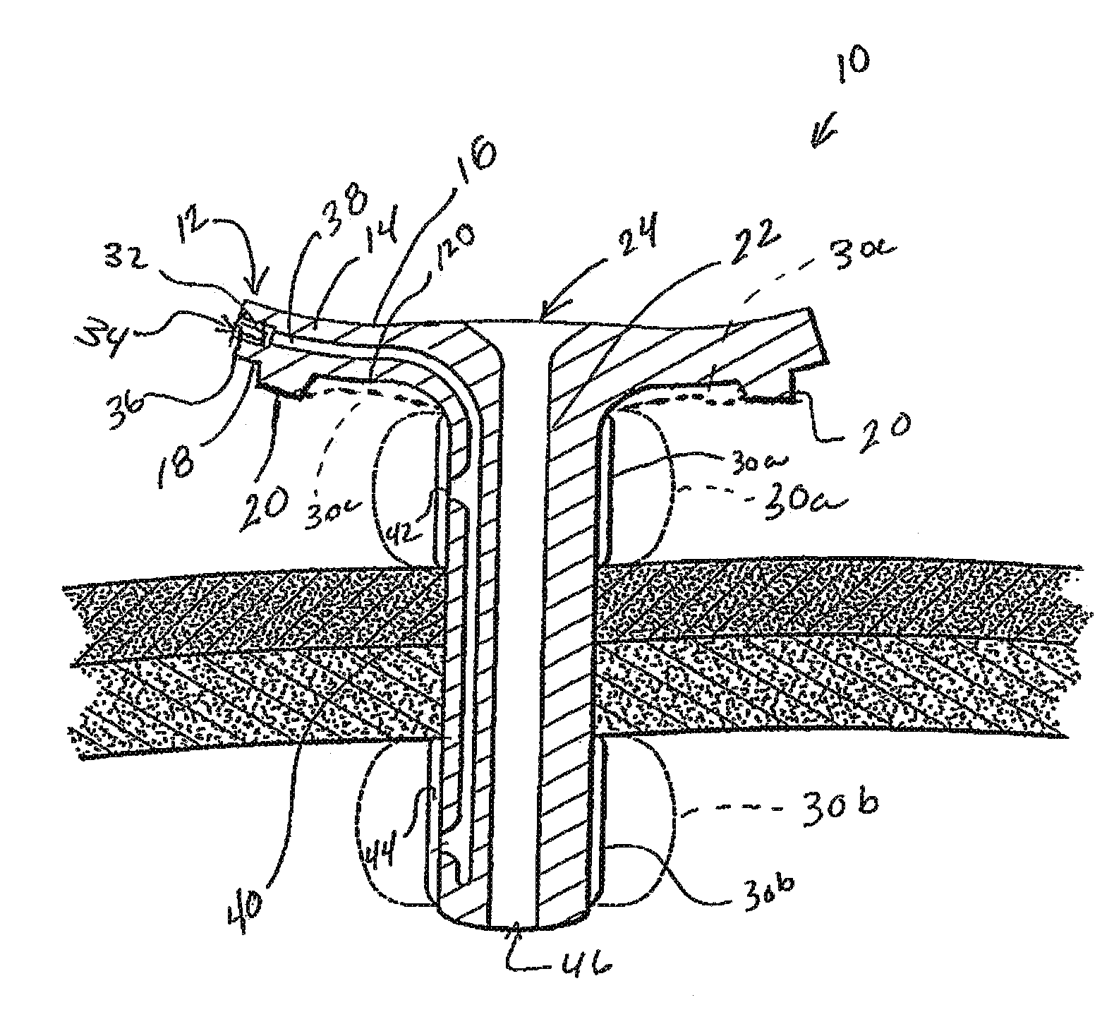
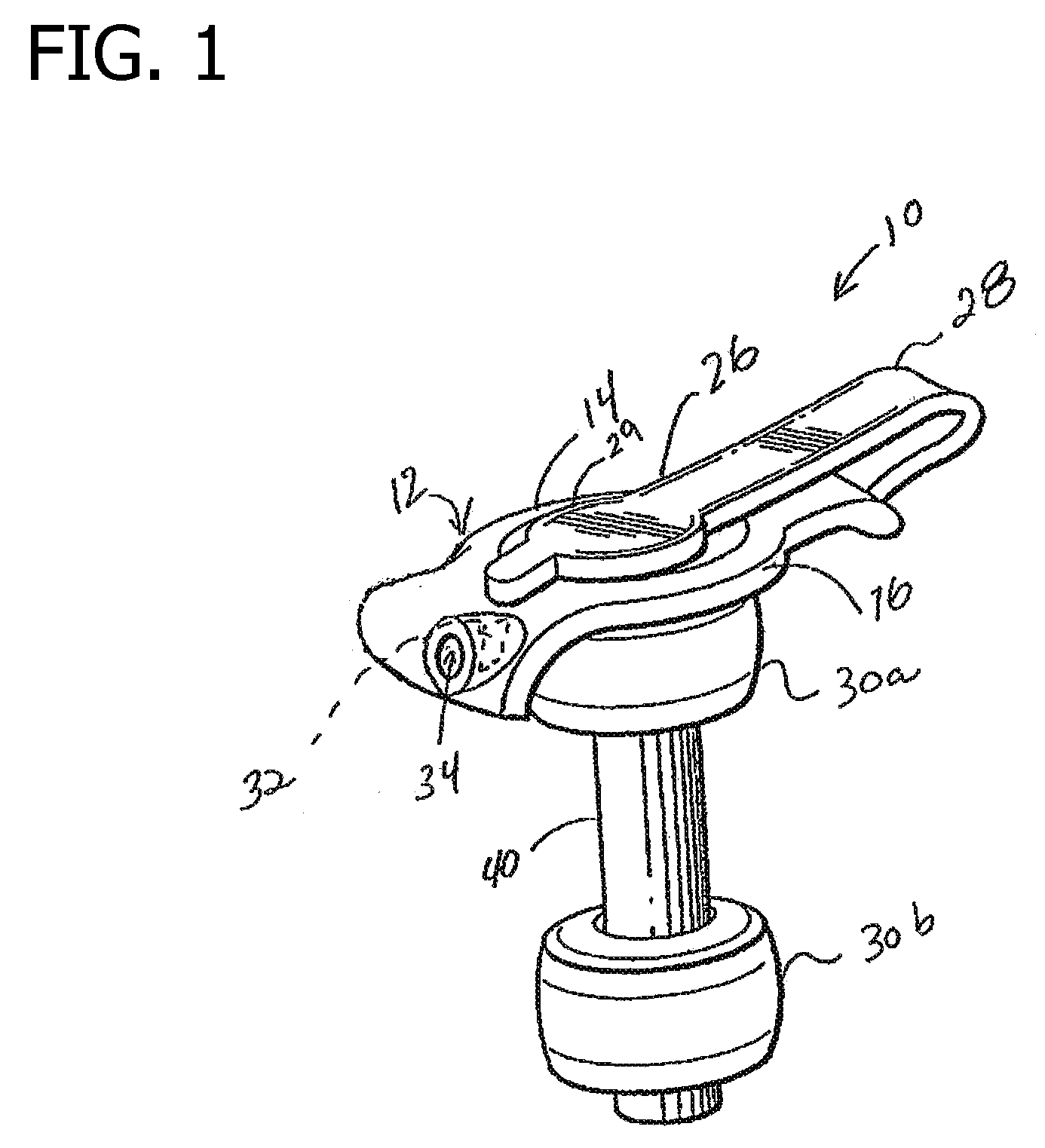
[0017]Referring to the drawings, a first embodiment of a low profile gastrostomy tube according to the present disclosure is illustrated and generally indicated as 10 in FIG. 1. The gastrostomy tube 10 may be configured for use with low profile gastrointestinal feeding systems. Known low profile gastrointestinal feeding systems suitable for use with the gastrostomy tube 10 of the present disclosure typically include a feeding set (not shown) having an elongate tube attachable to a fluid source and a connection member for securing the elongate tube to, for example, a low profile gastrostomy tube 10. A more detailed description of a feeding set suitable for use with the gastrostomy tube 10 of the present disclosure is provided in commonly owned U.S. Pat. Nos. 7,070,587 and 6,045,536 both to Meier et al., both of which are incorporated herein by reference in their entirety.

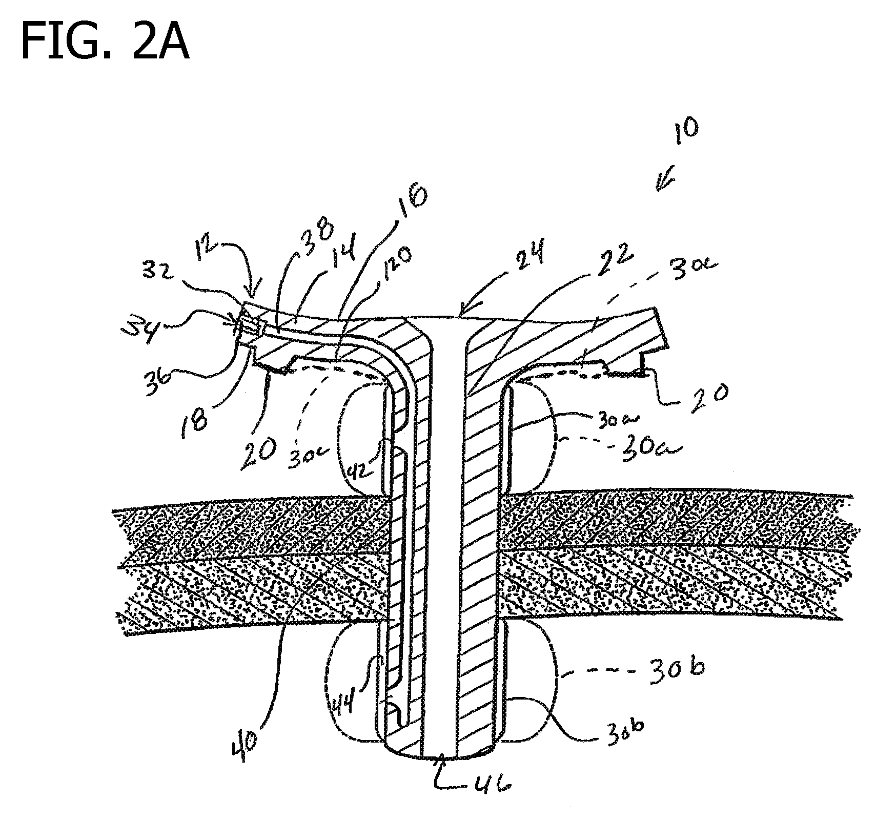
[0018]Referring to FIGS. 1 and 2A, the gastrostomy tube 10 includes a body 12 having a hub portion 14 (hub 14) and...


PUM


Abstract

A gastrostomy tube including a body having a hub portion and a tubular portion. The body defines a primary lumen having a first end in communication with an opening in the hub portion. The primary lumen has a second end in communication with an opening located in the tubular portion. The tube also includes a port supported on the body communicating with a secondary lumen. The port is adapted to engage an end of a luer tip syringe. The tube includes an external balloon located at a proximal end of the body. The tube has an internal balloon located distally from the external balloon. The internal and external balloons are in fluid communication with the port via the secondary lumen such that each is inflatable. The internal and external balloons enable a clinician to indirectly observe the internal balloon by observing the external balloon.

Description

CROSS-REFERENCE TO RELATED APPLICATIONS[0001]The present application is a non-provisional of U.S. Patent Application Ser. No. 61 / 101,231, filed Sep. 30, 2008, and entitled, “Skin Level Device for Use with Gastrostomy Tube”, which is hereby incorporated by reference in its entirety.FIELD OF THE INVENTION[0002]The present disclosure relates to gastrostomy tubes and, more particularly, to gastrostomy tubes including a skin level device having an expandable balloon and pad.BACKGROUND OF THE INVENTION[0003]Low profile gastrointestinal feeding systems are frequently used for long term tube fed patients who are mobile and / or combative and who require some type of gastrostomy device to provide nutrition to their stomachs. These gastrointestinal systems may include a feeding set having a nutrition source attached to one end and a low profile gastrostomy tube connected to the other end.[0004]The low profile gastrostomy tube is normally inserted through an established, mature stoma extending t...

Claims


Application Information

Patent Timeline
IPC IPC(8): A61M25/10A61F2/958
CPCA61J15/0015A61J15/0042A61M2025/0233A61J15/0073A61M25/1011A61J15/0065
Inventor SWISHER, DAVID RORK
Owner TYCO HEALTHCARE GRP LP
Why Eureka
Try Eureka