
Systems and Methods for Compensating for Large Moving Objects in Magnetic-Tracking Environments

a technology of moving objects and magnetic tracking, applied in the field of magnetic tracking, can solve problems such as significant inaccuracies in the determination of p&o and magnetic field distortion

Active Publication Date: 2010-04-01
ASCENSION TECH
View PDF4 Cites 38 Cited by
  • Summary
  • Abstract
  • Description
  • Claims
  • Application Information

AI Technical Summary

Problems solved by technology

A drawback of magnetic tracking technology is when a live imaging device, such as an X-ray image intensifier (a / k / a a “C-arm”), is used during the surgical procedure: the device causes significant inaccuracies in the determination of the P&O.
This inaccuracy is caused by the distortion of the magnetic field due to the metallic components of the imaging device, which are not accounted for (adequately, or at all) by the magnetic tracking algorithm being used.

Method used


Image

  • Systems and Methods for Compensating for Large Moving Objects in Magnetic-Tracking Environments
  • Systems and Methods for Compensating for Large Moving Objects in Magnetic-Tracking Environments
  • Systems and Methods for Compensating for Large Moving Objects in Magnetic-Tracking Environments

Examples


Embodiment Construction

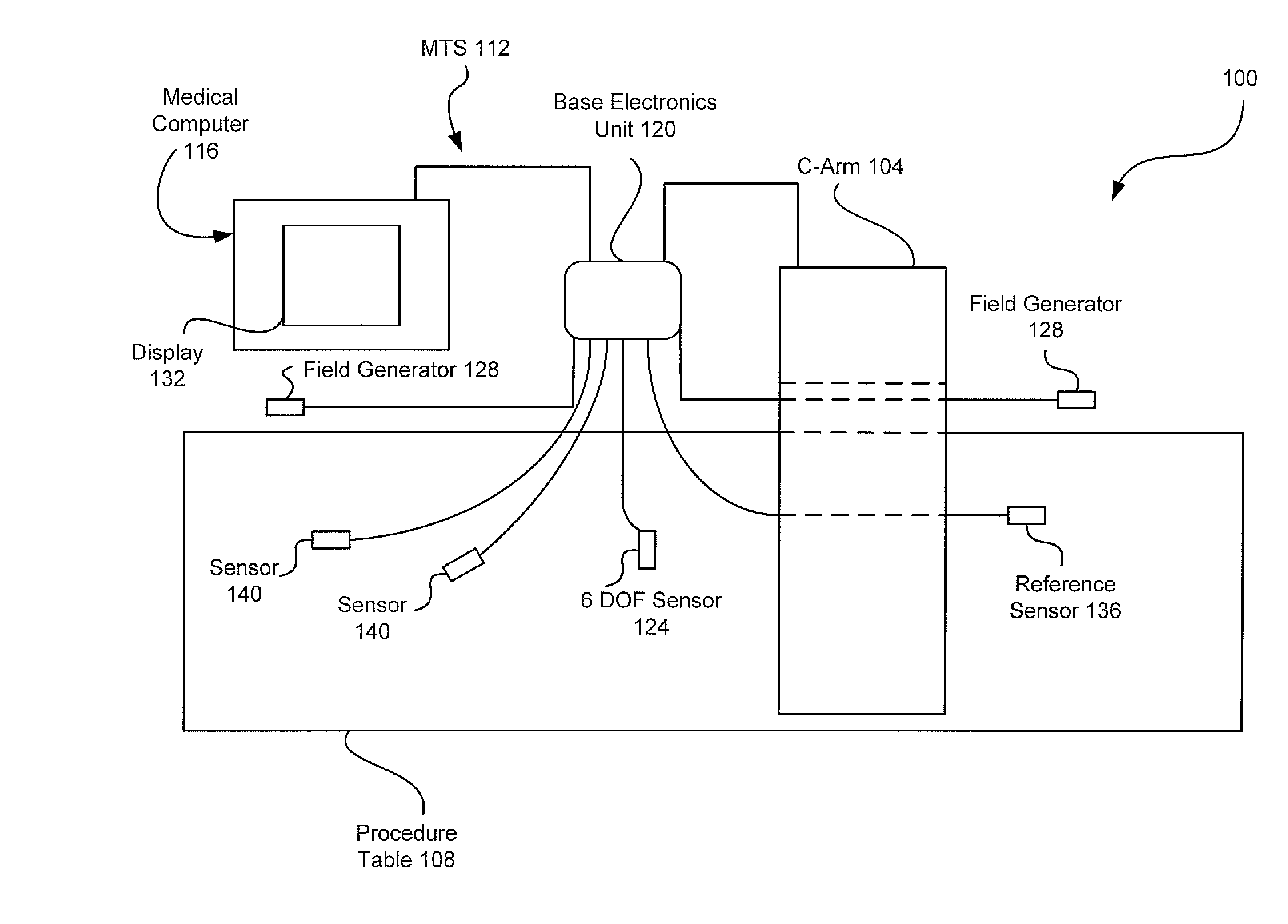
[0017]This application discloses novel methods of improving the accuracy of magnetic tracking systems (MTSs) when in the presence of one or more large, movable objects. Referring now to the drawings, FIG. 1 illustrates an exemplary setting, here a surgical setting 100, in which any one of the novel methods of the present disclosure may be implemented. As those skilled in the art will readily appreciate, surgical setting 100 is but one example of settings in which a method of the present disclosure may be implemented and other settings will be recognizable to a skilled artisan. Other settings include helmet mounted sights used in both actual and simulated cockpits, VR applications (e.g., the CAVE), and labor and delivery assistive technology, to name a few. In this example, surgical setting 100 includes a C-arm 104, which constitutes the large, movable object mentioned above. Surgical setting 100 also includes a procedure table 108, an MTS 112 and a medical computer 116, among other ...


PUM


Abstract

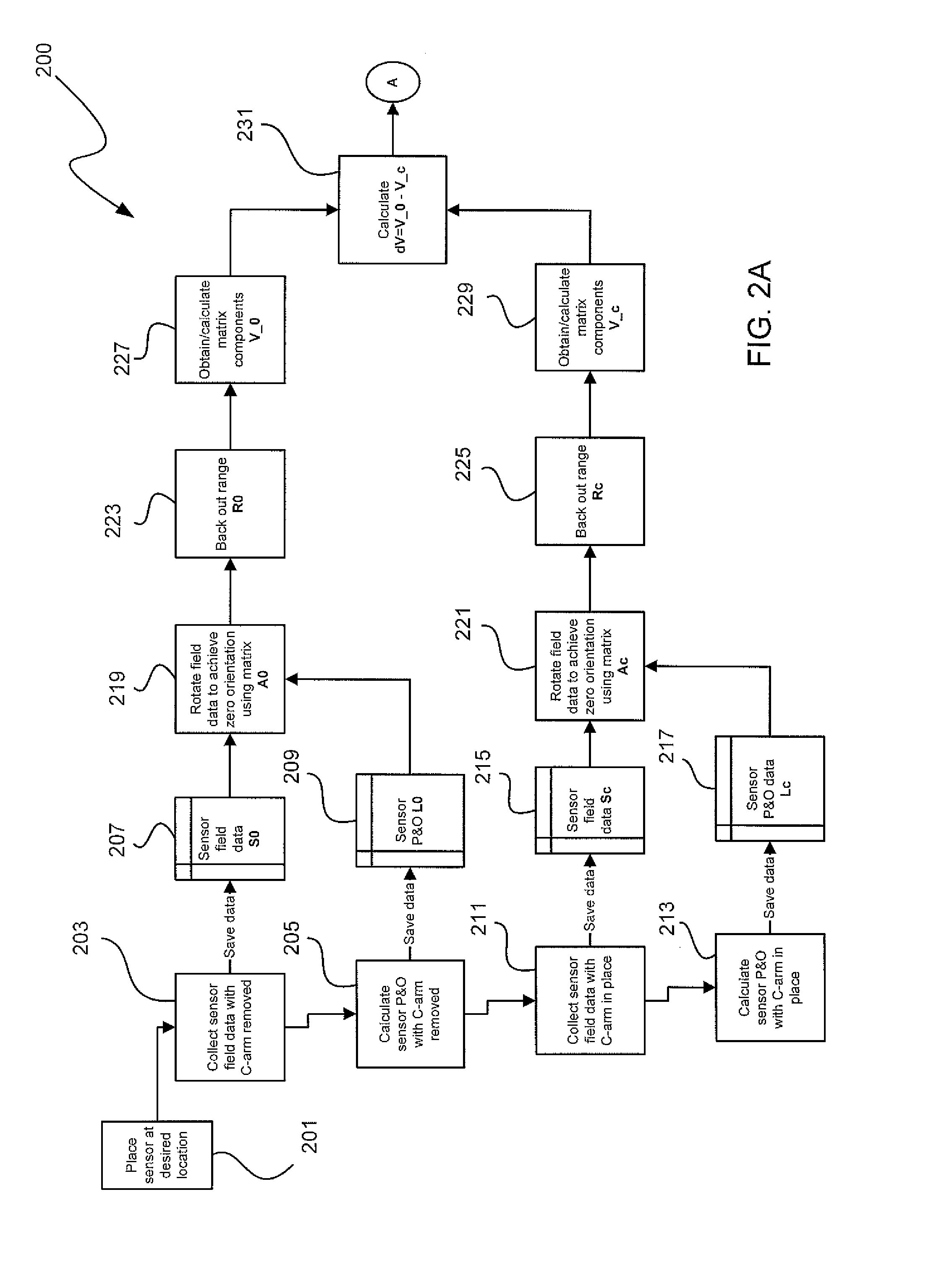
Methods for accurately tracking position and orientation of a magnetic-field sensor in a tracking volume when a large magnetic-field distorter is present in the tracking volume. In some of the methods, magnetic field data is collected from within the tracking volume both with and without the large magnetic-field distorter present in the tracking volume. This data is used to obtain correction information that is subsequently used during real-time operation of the magnetic-field sensor to correct the position and orientation solutions for the sensor for magnetic-field distortions caused by the presence of the large magnetic-field distorter in the tracking volume. Others of the methods involve modeling the large magnetic-field distorter using dipole and multipole modeling. Magnetic tracking systems for implementing the methods include hardware and software for carrying out the methods.

Description

RELATED APPLICATION DATA[0001]This application is a continuation-in-part of International Application No. PCT / US08 / 65263, filed May 30, 2008, and titled “Systems and Methods for Compensating for Large Moving Objects in Magnetic-Tracking Environments,” that claims the benefit of priority of U.S. Provisional Patent Application Ser. No. 60 / 942,009, filed Jun. 5, 2007, and titled “Method Of Compensating For Large Moving Objects In Electromagnetic Tracking Environments.” Each of these applications is incorporated by reference herein in its entirety.FIELD OF THE INVENTION[0002]The present invention generally relates to the field of magnetic-tracking. In particular, the present invention is directed to systems and methods for compensating for large moving objects in magnetic-tracking environments.BACKGROUND[0003]Image-guided surgical procedures typically require placing surgical instruments, for example, catheters, scopes, probes, needles, ultrasound, ablators, drills, therapy delivery, th...

Claims


Application Information

Patent Timeline
Patent Type & Authority Applications(United States)
IPC IPC(8): G06F19/00A61B5/05
CPCA61B5/06A61B5/726A61B19/5244A61B6/4441A61B2019/5251A61B2019/5458A61B2017/00725A61B5/062A61B34/20A61B2034/2051A61B2090/3958
Inventor SCHNEIDER, MARK R.
Owner ASCENSION TECH
Learn More