

Controller of vehicle with hydrostatic continuously variable transmission
- Summary
- Abstract
- Description
- Claims
- Application Information
AI Technical Summary
Benefits of technology
Problems solved by technology
Method used
Image

Examples
Embodiment Construction
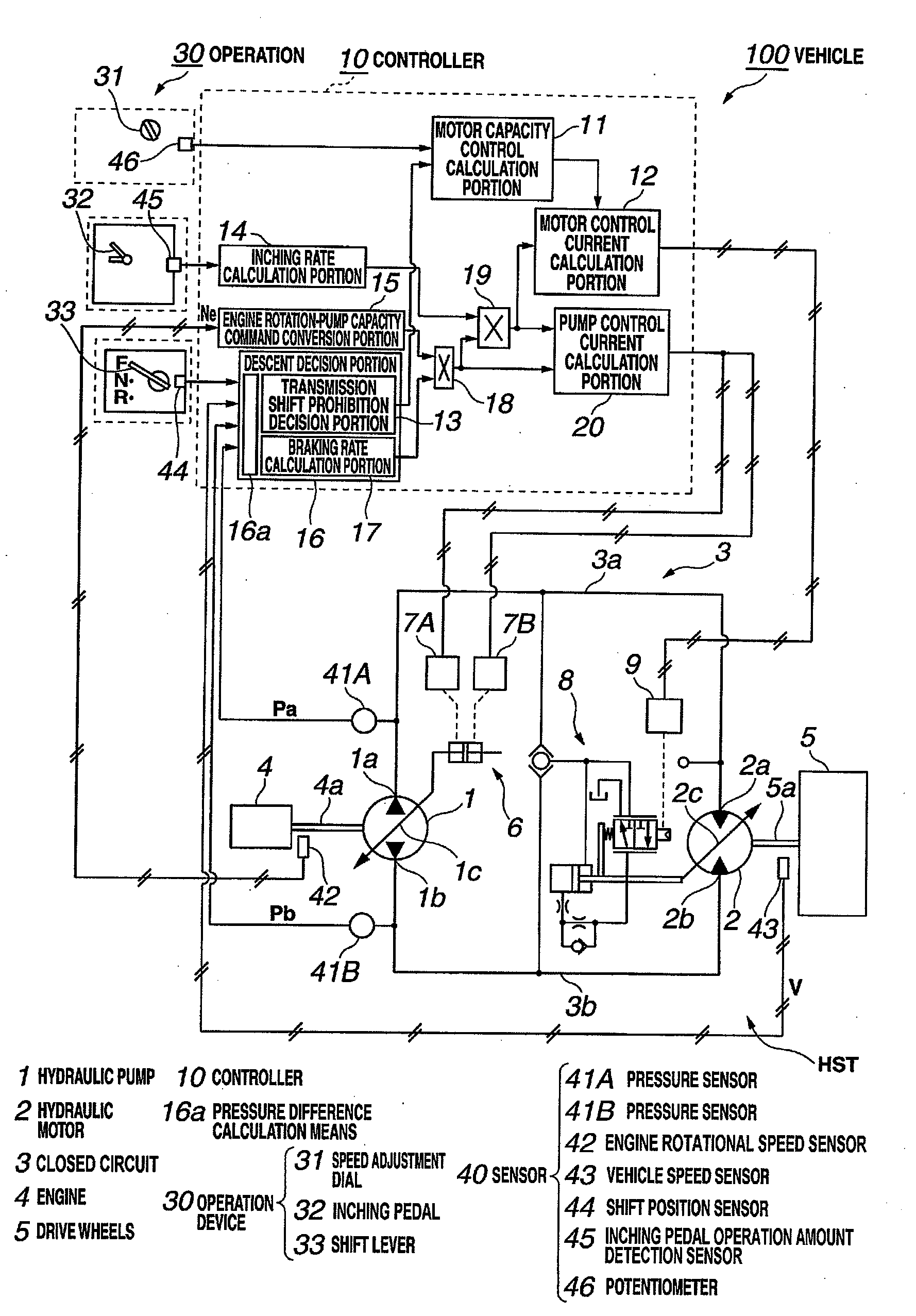
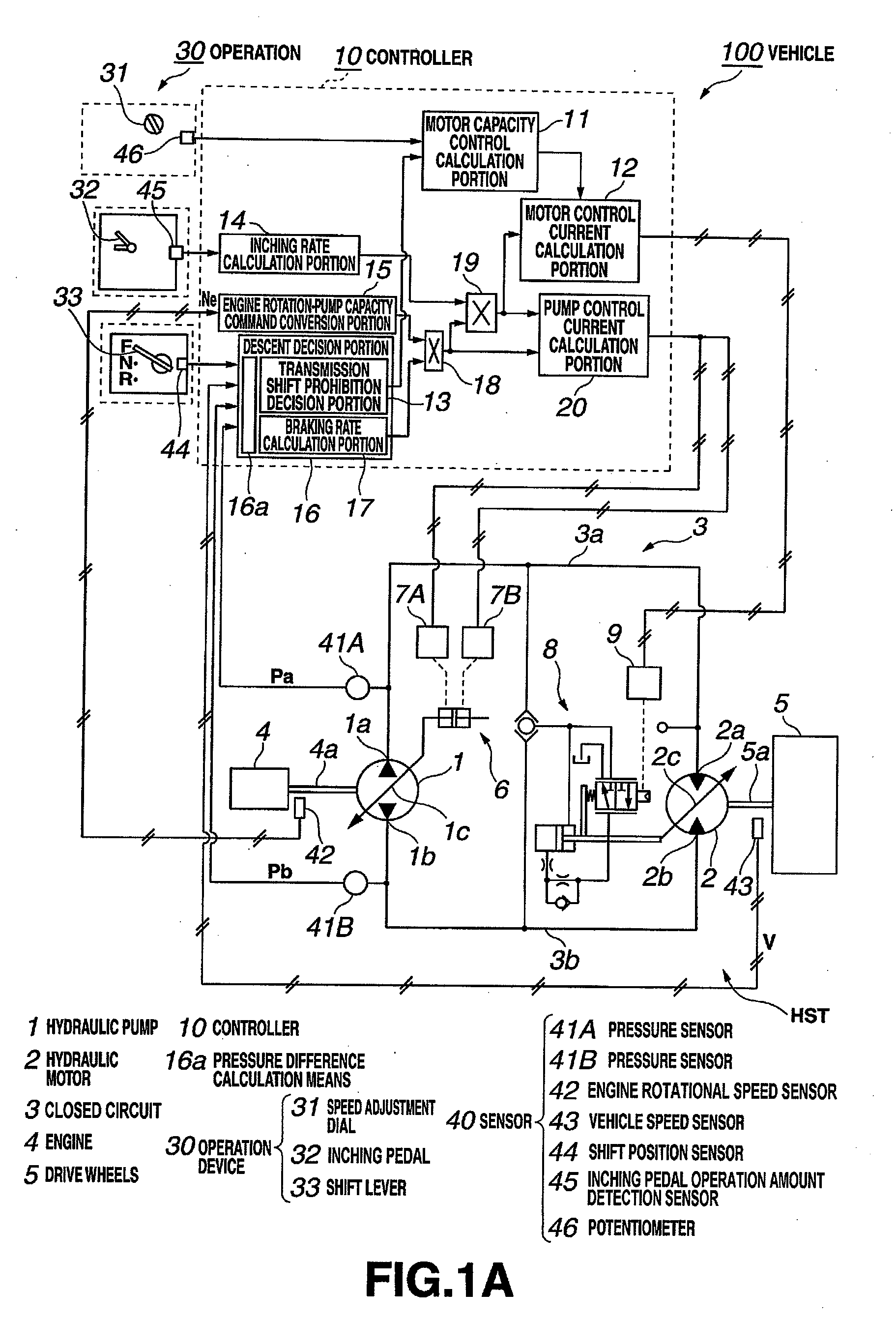
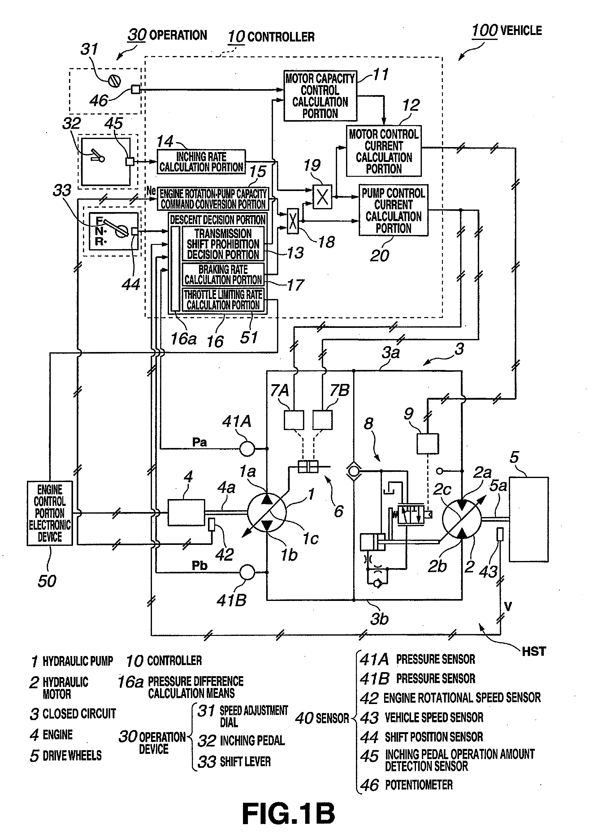
[0033]Below, a first exemplary embodiment of the present invention is explained, referring to the drawings.
[0034]FIG. 1A shows the configuration of the hydrostatic continuously variable transmission (HST) of the embodiment, a controller 10 which controls the HST, an operation device 30, and sensors 41A, 41B, 42, 43. This HST, the controller 10, the operation device 30, and the sensors 40 (41A, 41B, 42, 43, 44, 45, 46) are provided in a vehicle 100. As the vehicle 100, a wheel loader, a wheel tractor-scraper, a bulldozer, a forklift, or similar work vehicle is assumed.
[0035]As shown in FIG. 1A, the closed-circuit HST includes the hydraulic pump 1, the input shaft of which is connected to the output shaft 4a of the engine 4; the hydraulic motor 2, the output shaft of which is connected to the drive wheels 5 via the drive shaft 5a; and, the closed circuit 3, linking the hydraulic pump 1 and the hydraulic motor 2.
[0036]The closed circuit 3 includes the oil path 3a and the oil path 3b. T...
PUM
 Abstract
Description
Claims
Application Information