Comparing method and laser processing apparatus

Active Publication Date: 2021-01-28
DISCO CORP
View PDF0 Cites 1 Cited by
  • Summary
  • Abstract
  • Description
  • Claims
  • Application Information

AI Technical Summary

Benefits of technology

This patent is about a method for measuring the shapes of processing traces on a surface of a workpiece using a laser beam. The method involves creating multiple processing traces on the surface at different heights and imaging them using a camera to obtain an image. The image is then analyzed to calculate the average width and area ratio of each processing trace in different directions. This allows for a quicker and more accurate way to measure the shapes of processing traces compared to traditional methods where workers have to manually measure and prepare graphs. Additionally, the method allows for quantitative comparison of the shapes of different processing traces by calculating the average width and area ratio and eliminating the effect of workers' measurements. Overall, this method reduces the time needed for preparing and measuring graphical data and ensures consistency in the analysis of processing trace shapes.

Problems solved by technology

However, in a case where a worker prepares the first and second graphs, much time is taken to measure the lengths in the longitudinal and lateral directions of the processing traces.
Further, there is no reference for directions in which to measure the lengths of a dot-shaped processing trace in a case where the processing trace has a shape distorted from a perfect circle.

Method used


Image

  • Comparing method and laser processing apparatus
  • Comparing method and laser processing apparatus
  • Comparing method and laser processing apparatus

Examples


Embodiment Construction

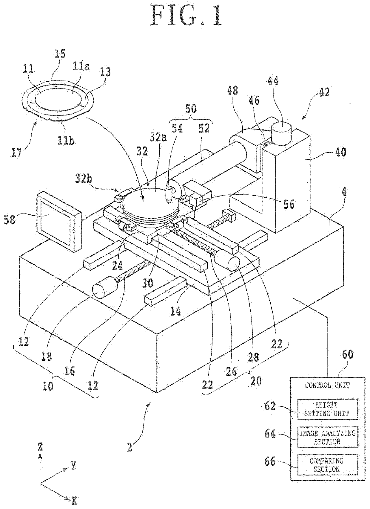
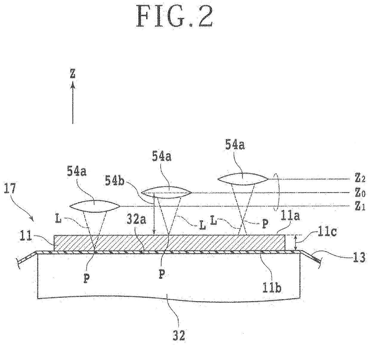
[0021]An embodiment according to one aspect of the present invention will be described with reference to the accompanying drawings. A wafer 11 as a workpiece will be described first. The wafer 11 is, for example, formed of silicon. The wafer 11 has a flat top surface (one surface) 11a and a flat undersurface (another surface) 11b. The wafer 11 has a disk shape. The wafer 11 has a thickness of approximately 100 μm from the top surface 11a to the undersurface 11b. Incidentally, the material of the wafer 11 is not limited to only silicon. The wafer 11 may be a laminated substrate formed by laminating one surface of a sapphire substrate and one surface of a silicon substrate to each other. In addition, the wafer 11 is not limited to a disk shape, but may be of a rectangular shape.

[0022]A dicing tape 13 made of a resin which dicing tape has a diameter larger than that of the wafer 11 is affixed to the undersurface 11b side of the wafer 11. The dicing tape 13, for example, has a laminated...


PUM


Abstract

A comparing method includes a processing trace forming step of positioning a condenser at a reference height and a plurality of heights by moving the condenser, and forming a plurality of processing traces in one surface of a workpiece by irradiating different positions of the one surface with a laser beam according to each of the heights, a calculating step of calculating at least one of an average of widths in a plurality of predetermined directions of each of the plurality of processing traces and an area ratio of each of the plurality of processing traces to a circle of a predetermined diameter by analyzing an image of the plurality of processing traces by an image analyzing section, and a comparing step of quantitatively comparing deviations of the plurality of processing traces from a predetermined shape on the basis of at least one of the average and the area ratio.

Description

BACKGROUND OF THE INVENTIONField of the Invention[0001]The present invention relates to a comparing method of forming a plurality of processing traces in one surface of a workpiece, and quantitatively comparing deviations of the plurality of processing traces from a predetermined shape, and a laser processing apparatus including an image analyzing section that analyzes an image of a plurality of processing traces formed in one surface of a workpiece.Description of the Related Art[0002]A processing method is known which forms processed grooves in a wafer formed by a semiconductor material such as silicon or the like by applying a pulsed laser beam having a wavelength absorbed by the wafer along planned dividing lines set on the top surface side of the wafer (see Japanese Patent Laid-Open No. 2007-275912, for example). This processing method uses a laser processing apparatus. The laser processing apparatus includes a chuck table that sucks and holds the undersurface side of the wafer....

Claims


Application Information

Patent Timeline
IPC IPC(8): H01L21/66H01L21/268H01L21/67
CPCH01L22/12H01L21/67115H01L21/268B23K26/36B23K26/0861B23K26/702H01L21/78B23K26/0006B23K26/032B23K26/0853B23K26/0869B23K2103/56B23K26/359B23K26/364B23K26/707B23K26/382H01L21/67092H01L21/3043
Inventor KAWANO, FUMIYAKOYANAGI, TASUKUMORIKAZU, HIROSHI
Owner DISCO CORP
Why Eureka
Try Eureka