Lithium Ion Storage Device

Inactive Publication Date: 2012-04-05
SHIN KOBE ELECTRIC MASCH
View PDF3 Cites 2 Cited by
  • Summary
  • Abstract
  • Description
  • Claims
  • Application Information

AI Technical Summary

Benefits of technology

[0009]Another object of the present invention is to provide a lithium ion storage device in which a negative active material of a negative plate may securely be doped with lithium ions generated by dissolving a lithium metal plate disposed in an electrode group.
[0016]The conductive shielding member, which is formed by forming the negative active material layer on one surface of the current collecting metal foil, may be used in an unfolded state. In this case, the thin lithium metal plate may be affixed to the other surface of the current collecting metal foil. Then, the conductive shielding member may be disposed in the electrode group with the other surface of the current collecting metal foil facing toward the negative plate. This configuration causes the effect of increasing the capacity compared to the aforementioned configuration of the conductive shielding member.

Problems solved by technology

This configuration also reduces the number of working processes for manufacturing the conductive shielding member and shortens the working time, compared to when the negative active material layer is formed on both surfaces of the current collecting metal foil.

Method used


Image

  • Lithium Ion Storage Device
  • Lithium Ion Storage Device
  • Lithium Ion Storage Device

Examples


first embodiment

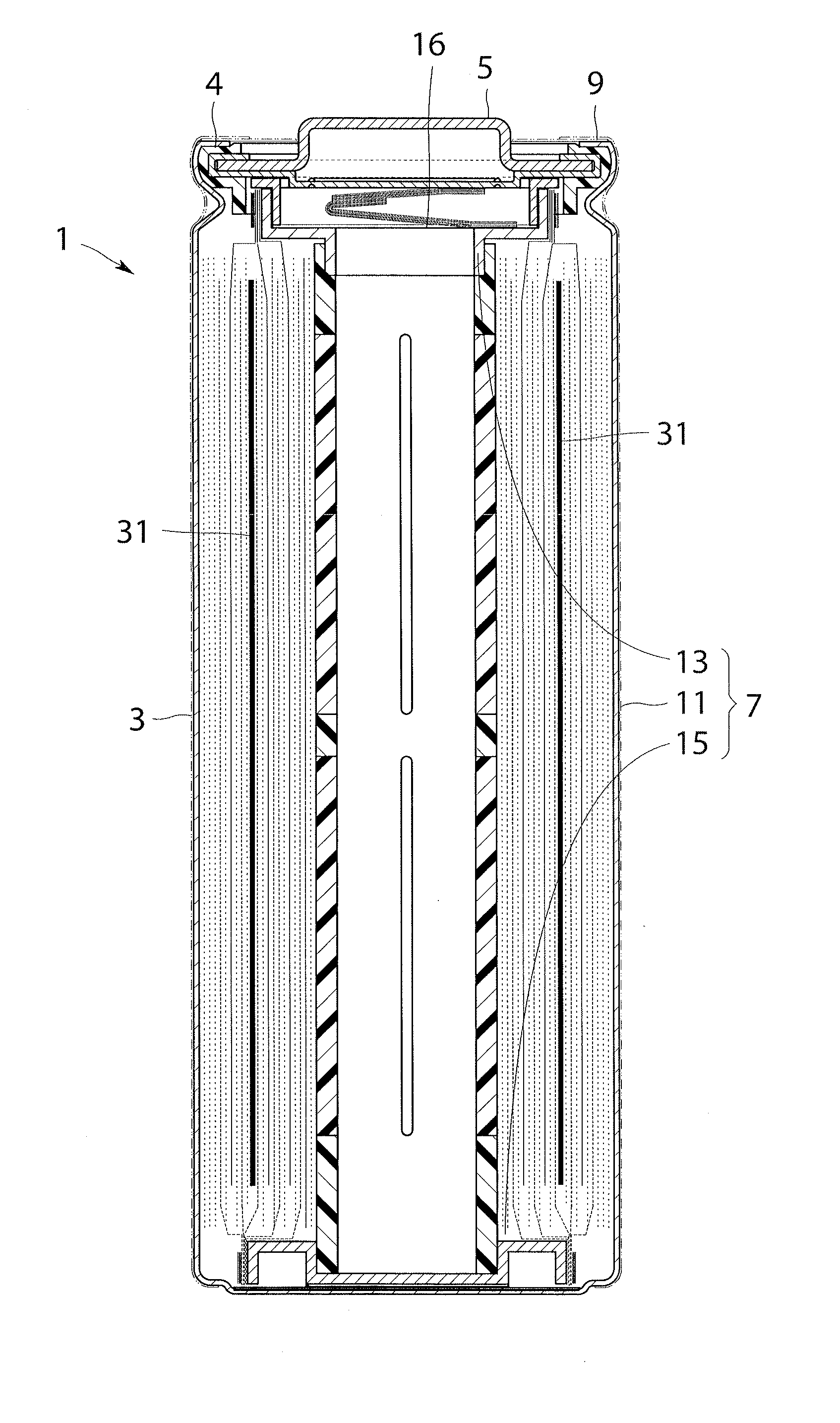
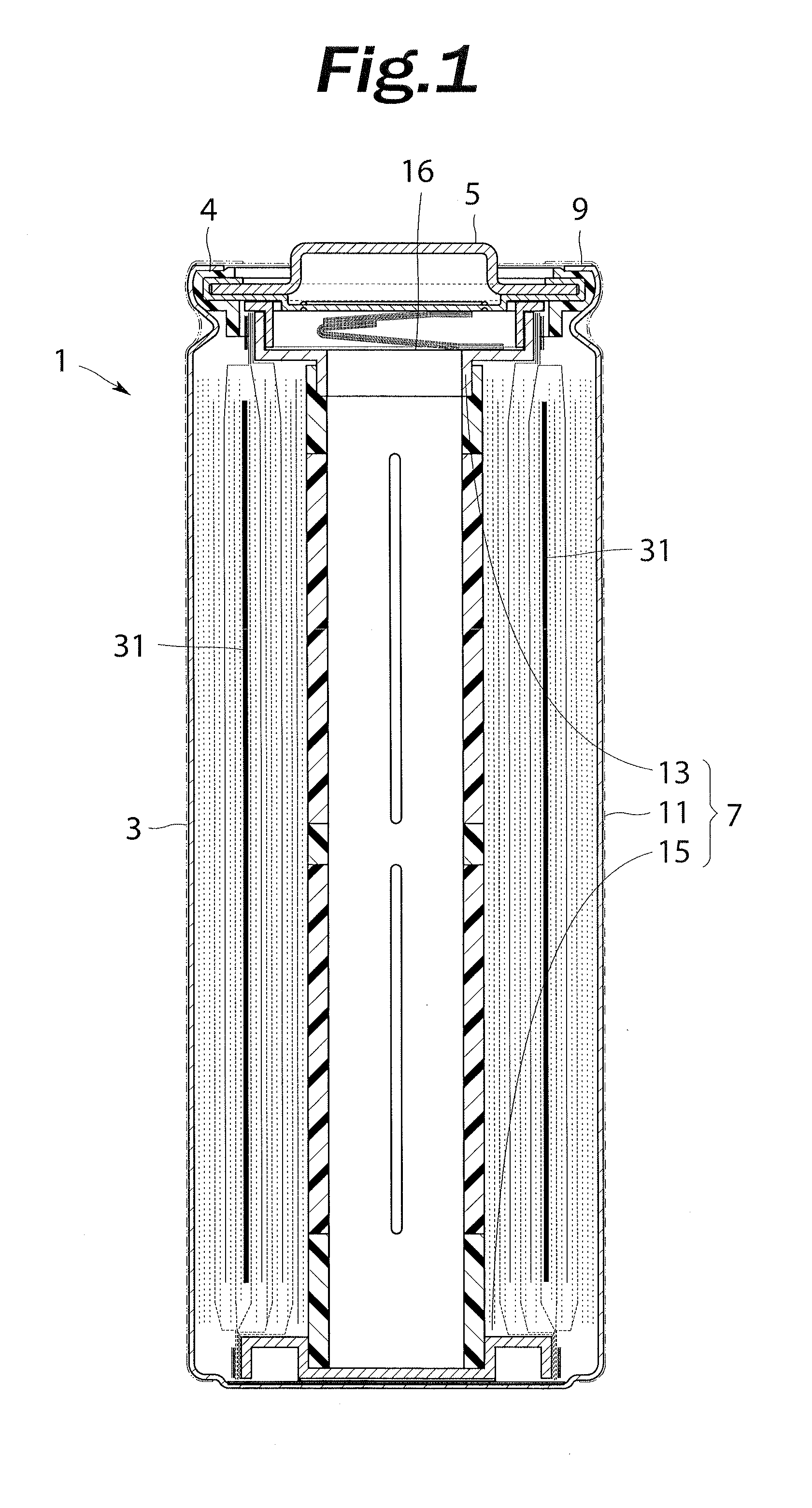
[0021]Embodiments of the present invention will be described in detail below with reference to the drawings. FIG. 1 is a cross-sectional view of a cylindrical lithium ion capacitor according to the present invention taken along the longitudinal direction. In FIG. 1, some of the constituent members of the lithium ion capacitor are not shown. A cylindrical lithium ion capacitor 1 according to the embodiment includes a container body 3, a lid member 5, and an electrode group unit 7. The container body 3 is made of a nickel-plated steel material, and has the shape of a bottomed cylinder with one open end portion. An opening portion 4 of the container body 3 is closed by the lid member 5. The lid member 5 is swaged in the open end portion of the container body 3 via a gasket 9 made of a rubber or a resin having insulation and heat-resistance properties. Therefore, the internal space of the capacitor 1 is hermetically sealed. An non-aqueous electrolyte (not shown) is poured into the capac...

second embodiment

[0033]FIG. 3A schematically shows an electrode group 111 before being wound, which is used in a cylindrical lithium ion capacitor according to the present invention. FIG. 3B shows a lithium metal plate 131, a conductive shielding member 133, and a perforated copper foil 151, which are disposed in the electrode group 111, as enlarged. In FIGS. 3A and 3B, component parts that are similar to those shown in FIGS. 1, 2A, and 2B are denoted by reference numerals obtained by adding 100 to the reference numerals affixed to their counterparts in FIGS. 1, 2A, and 2B to omit detailed descriptions.

[0034]In the electrode group 111 used in the cylindrical lithium ion capacitor according to the second embodiment, as shown in FIGS. 3A and 3B, the lithium metal plate 131 is not directly affixed to a negative plate 119, and the lithium metal plate 131 is indirectly disposed on the negative plate 119 via the perforated copper foil 151. The perforated copper foil 151 used in the embodiment is formed to...

third embodiment

[0035]FIG. 4A schematically shows an electrode group 211 before being wound, which is used in a cylindrical lithium ion capacitor according to the present invention. FIG. 4B shows a lithium metal plate 231 and a conductive shielding member 233, which are disposed in the electrode group 211, as enlarged. In FIGS. 4A and 4B, component parts that are similar to those shown in FIGS. 1, 2A, and 2B are denoted by reference numerals obtained by adding 200 to the reference numerals affixed to their counterparts in FIGS. 1, 2A, and 2B to omit detailed descriptions.

[0036]In the cylindrical lithium ion capacitor according to the third embodiment, as shown in FIGS. 4A and 4B, the lithium metal plate 231 is disposed in the electrode group 211 such that the lithium metal plate 231 is sandwiched in the conductive shielding member 233 in a folded state. The conductive shielding member 233 according to the embodiment is configured such that a negative active material layer (not shown) is formed on o...


PUM


Abstract

A present invention provide a lithium ion storage device capable of reliably doping a negative active material of a negative plate with lithium ions generated through dissolution of a lithium metal plate disposed in an electrode group. A conductive shielding member includes a current collecting metal foil and a negative active material layer formed on at least one surface of the current collecting metal foil. The conductive shielding member is provided between a lithium metal plate and a positive plate such that the lithium metal plate is sandwiched between the negative plate and the negative active material layer formed on the current collecting metal foil of the conductive shielding member.

Description

BACKGROUND OF THE INVENTION[0001]1. Field of the Invention[0002]The present invention relates to a lithium ion storage device.[0003]2. Description of the Related Art[0004]Lithium ion storage devices such as lithium ion capacitors and lithium ion batteries advantageously have a high energy density, a low self-discharge rate, and good cycle performance. Therefore, in recent years, it has been expected to increase the size and the capacity of non-aqueous electrolyte storage devices to use such storage devices as power sources for automobiles such as hybrid vehicles and electric vehicles. In some lithium ion storage devices, a negative plate is doped with lithium ions in advance (lithium pre-doping) to expand the voltage range of use and to increase the capacity.[0005]One method for doping a negative plate with lithium ions in advance is, for example, to place a lithium metal plate in an electrode group before doping, dissolve the lithium metal plate to generate lithium ions, and dope a...

Claims


Application Information

Patent Timeline
IPC IPC(8): H01G9/048H01G9/15H01M4/66H01G11/06H01G11/22H01G11/30H01G11/66H01G11/70H01M4/13H01M10/0525H01M10/058
CPCH01G11/02H01G11/50H01M2/1673H01M4/13Y02E60/13H01M10/058Y02T10/7011Y02T10/7022Y02E60/122H01M10/052H01M50/46Y02E60/10Y02T10/70Y02P70/50H01M10/0525
Inventor SAKURAI, ATSUSHIUEHARA, HIDEAKIIIDA, YUKIOWAKAMATSU, YOSHIMIHOSHI, HARUKI
Owner SHIN KOBE ELECTRIC MASCH
Why Eureka
Try Eureka