Grinding apparatus

Pending Publication Date: 2021-08-12
DISCO CORP
View PDF0 Cites 0 Cited by
  • Summary
  • Abstract
  • Description
  • Claims
  • Application Information

AI Technical Summary

Benefits of technology

This invention is about a grinding apparatus that makes it easy to replace the grinding wheel. The apparatus has a mechanism that stops the nozzle from moving upward when the grinding unit moves to a higher position. This creates a gap between the mount and the nozzle, making it simple to replace the grinding wheel and save time.

Problems solved by technology

However, the nozzle disclosed in Japanese Patent Laid-open No. 2011-025380 is connected to the grinding unit and disposed directly below the grindstone, the nozzle serves as an obstacle at the time when the grindstone has been consumed and the grinding wheel on which the grindstone is disposed is to be replaced.

Method used


Image

  • Grinding apparatus
  • Grinding apparatus
  • Grinding apparatus

Examples


Embodiment Construction

[0017]An embodiment of the present invention will be described below referring to the attached drawings.[0018]1. Configuration of Grinding Apparatus

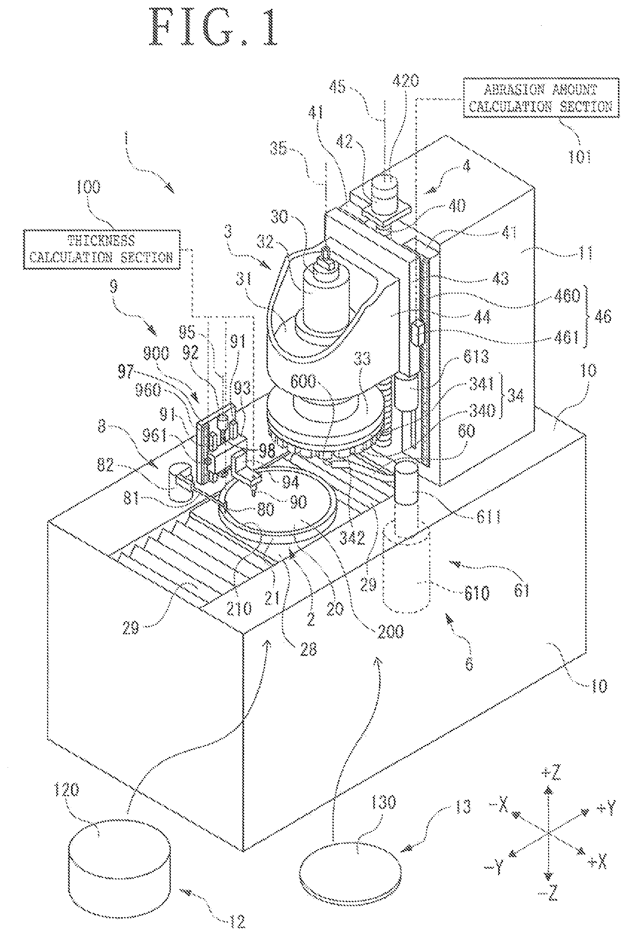
[0019]A grinding apparatus 1 depicted in FIG. 1 is a grinding apparatus for grinding an SiC ingot as an example of a workpiece or a wafer 13 formed by slicing the ingot 12 into an appropriate thickness by use of a grindstone 340.

[0020]As depicted in FIG. 1, the grinding apparatus 1 includes a base 10 extended in a Y-axis direction, and a column 11 erected at a +Y direction side position on the base 10.

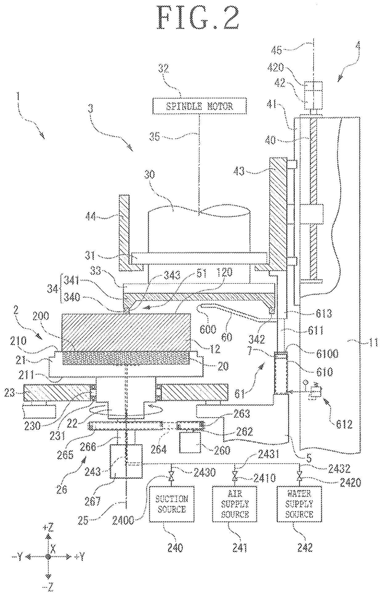
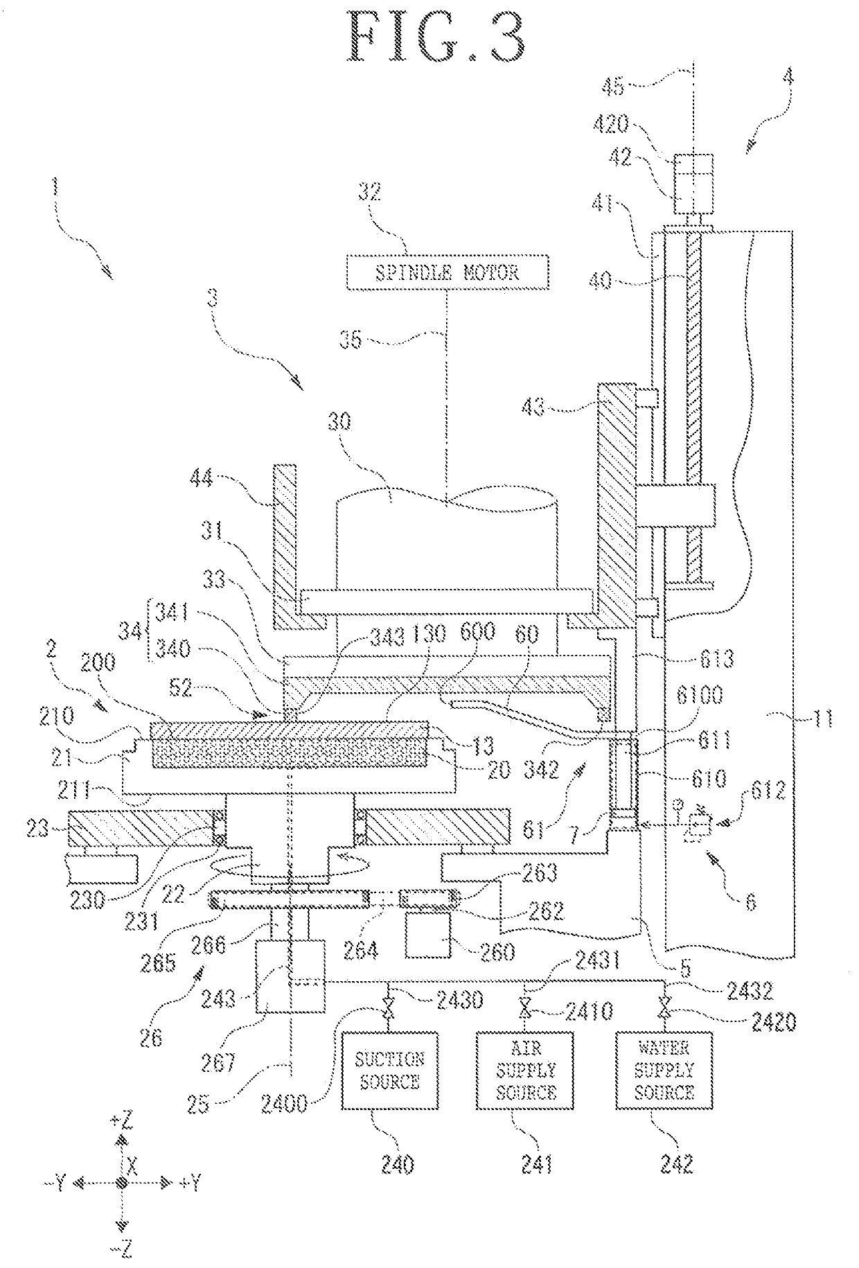
[0021]A grinding feeding mechanism 4 supporting a grinding unit 3 is disposed on a side surface on a −Y direction side of the column 11. The grinding unit 3 includes a spindle 30 having a rotational axis 35 parallel to a Z-axis direction, a housing 31 supporting the spindle 30 in a rotatable manner, a spindle motor 32 rotationally driving the spindle 30 with the rotational axis 35 as an axis, an annular mount 33 connected to a lower end of ...


PUM


Abstract

A grinding apparatus includes a grinding unit, a grinding feeding mechanism, and a grinding water supply unit. The grinding water supply unit includes a nozzle that jets grinding water to grindstones, and a biasing mechanism that biases the nozzle upward. The nozzle is configured to be movable downward against the upward biasing according to a downward movement of the grinding unit. The grinding apparatus further includes an upper limit stopping section that sets an upper limit position for upward movement of the nozzle biased upward by the biasing mechanism, for forming a gap through which the grinding wheel is passed, between the nozzle and the mount.

Description

BACKGROUND OF THE INVENTIONField of the Invention[0001]The present invention relates to a grinding apparatus.Description of the Related Art[0002]As disclosed in Japanese Patent No. 6355540 and Japanese Patent No. 6090998, a laser beam is applied to an upper surface of an SiC ingot having an off angle, to form modified layers and cracks inclined by the off angle amount with the modified layers as start points at a predetermined depth position from the upper surface, and the SiC ingot is separated into a thick part and a thin part with the thus formed cracks as start points, whereby an SiC wafer consisting of the thin part is manufactured. Since the cracks are inclined by the off angle amount, the surface generated by the separation of the SiC ingot is rugged. In view of this, for enabling incidence of a laser beam for forming the next SiC wafer, the ruggedness is removed by grinding the upper surface of the SiC ingot by use of a grindstone.[0003]In such grinding, for cooling the grin...

Claims


Application Information

Patent Timeline
IPC IPC(8): B24B55/02
CPCB24B55/02
Inventor GENOZONO, JIRO
Owner DISCO CORP
Why Eureka
Try Eureka