Optical fiber fusion splicer

Active Publication Date: 2015-02-19
THE FUJIKURA CABLE WORKS LTD
View PDF5 Cites 12 Cited by
  • Summary
  • Abstract
  • Description
  • Claims
  • Application Information

AI Technical Summary

Benefits of technology

The optical fiber fusion splicer described in this patent allows for automatic and reliable opening and closing of a cover that serves as a windshield, which helps to shorten the time required for the fusion splicing of optical fibers and make the work more manageable.

Problems solved by technology

In addition, in a conventional fusion splicer, when mounting the optical fibers to be fusion-spliced or taking out the optical fibers after the completion of fusion splice in a state where the windshield cover is open, a risk of the optical fiber being broken due to being hooked to the windshield cover is increased.

Method used


Image

  • Optical fiber fusion splicer
  • Optical fiber fusion splicer
  • Optical fiber fusion splicer

Examples


first embodiment

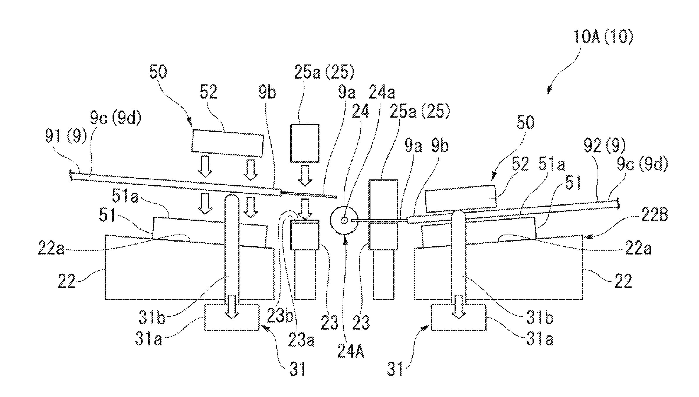
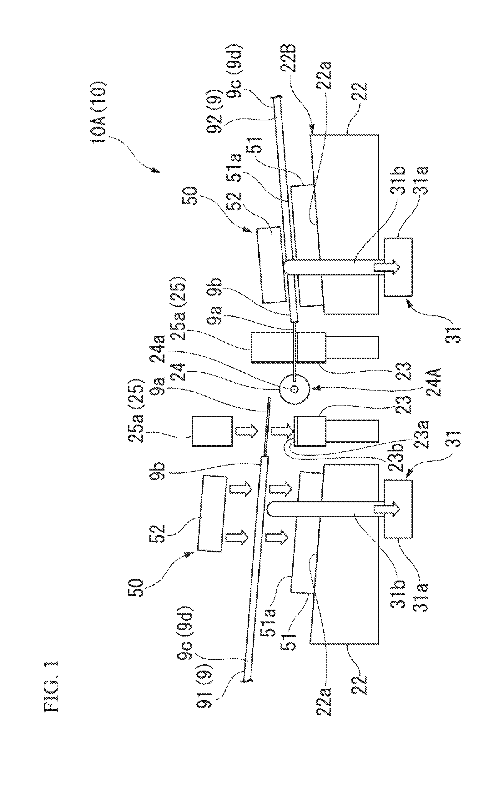
[0092]Hereinafter, an optical fiber fusion splicer (hereinafter, simply referred to as a fusion splicer) according to the present invention will be described with reference to the drawings.

[0093]FIG. 1 shows an example of the fusion splicer 10.

[0094]The fusion splicer 10 (denoted by the reference numeral 10A in the drawing) shown in FIG. 1 is an apparatus that fusion-splices a pair of optical fibers 9.

[0095]In FIG. 1, one of the pair of optical fibers 9 fusion-spliced by the fusion splicer 10A is denoted by the reference numeral 91, and the other one is denoted by the reference numeral 92.

[0096]The optical fiber 9 illustrated herein is a coated optical fiber, obtained by depositing a coating material 9c (coating) made of a synthetic resin on the outer periphery of an optical fiber glass portion 9a (bare optical fiber) and unifying them, such as an optical fiber core or an optical fiber stand.

[0097]As shown in FIGS. 1 and 3 to 6, on an apparatus body 20 having a box-shaped outer appe...

second embodiment

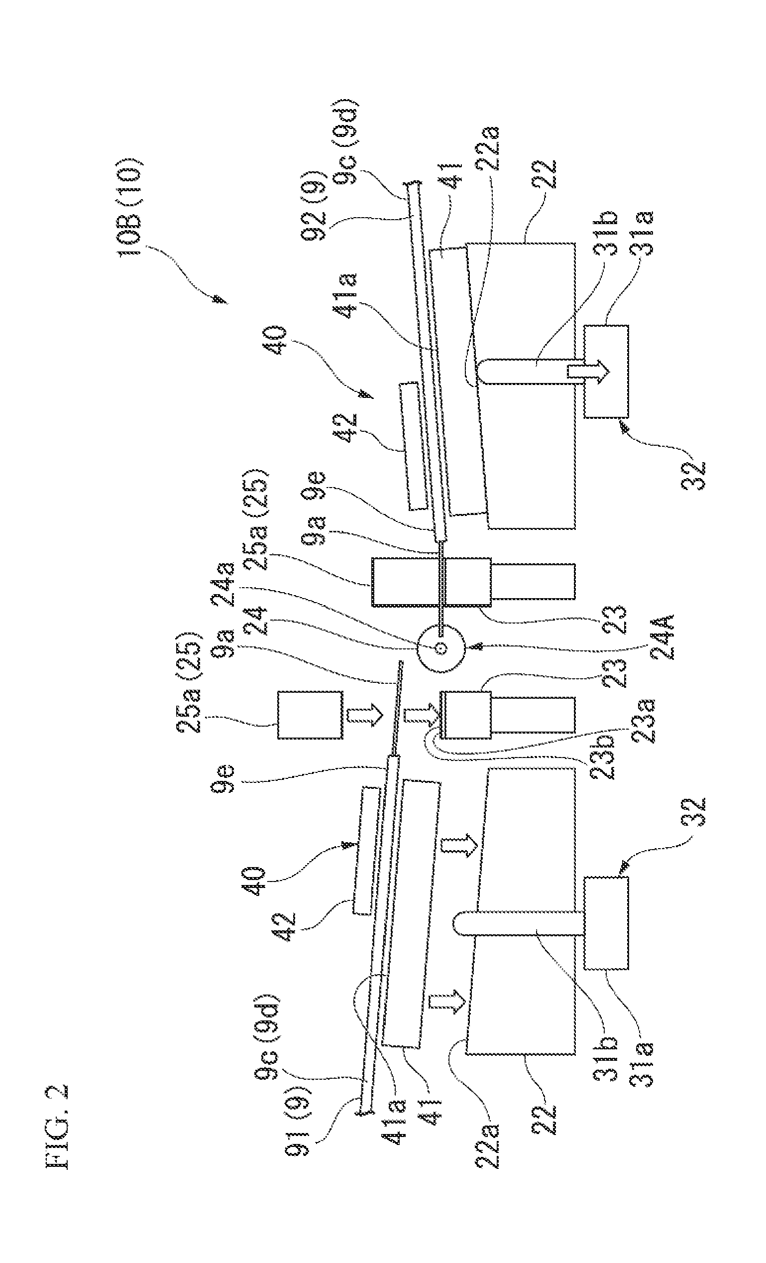
[0282]FIG. 2 is a fusion splicer 10 according to the present invention, and shows a configuration in which the coating clamp 50 provided on the movable stage 22 of the fusion splicer 10A illustrated in FIG. 1 is omitted and the movable stage 22 is used as a holder mounting portion to place the fiber holder 40, which holds and fixes the optical fiber 9, thereon.

[0283]The fusion splicer 10 according to the second embodiment of the present invention shown in FIG. 2 is denoted by reference numeral 10B.

[0284]The fiber holder 40 is placed on the movable stage 22, and is provided so as to be detachable from the movable stage 22.

[0285]As shown in FIGS. 2 and 9, the fiber holder 40 is configured to hold and fix the optical fiber 9 by pinching the optical fiber 9 between a base plate 41 and a cover plate 42 that is provided so as to be openable and closable in a state pivotally attached to the base plate 41, and is placed on the movable stage 22 that is provided in the fusion splicer 10B in a...


PUM


Abstract

An optical fiber fusion splicer includes: a windshield cover that is formed so as to be openable and closable and that includes one or more cover members that cover a heat fusion portion in a closed state; a pair of fiber mounting portions that are provided on left and right sides of the heat fusion portion; a pair of fiber mounting detectors that are provided in the fiber mounting portions and that detect that an optical fiber has been mounted. Also, when both the fiber mounting detectors detect that the optical fibers have been mounted in a state where the cover member is open, an operation to close the cover member is performed, the fusion splice is performed, connection portion inspection is performed, and an operation to open the windshield cover is performed after the connection portion inspection is completed.

Description

CROSS REFERENCE TO RELATED APPLICATIONS[0001]This application is a continuation application based on a PCT Patent Application No. PCT / JP2012 / 083080, filed Dec. 20, 2012, whose priority is claimed on Japanese Patent Application No. 2012-78259, filed Mar. 29, 2012, the entire content of which are hereby incorporated by reference.BACKGROUND OF THE INVENTION[0002]1. Field of the Invention[0003]The present invention relates to an optical fiber fusion splicer and in particular, to an optical fiber fusion splicer having an openable and closable windshield cover that covers a heat fusion portion for fusion-splicing optical fibers by heating.[0004]2. Description of the Related Art[0005]As an optical fiber fusion splicer, an apparatus (single-core machine) which fusion-splices a pair of optical fibers facing each other in the longitudinal direction by performing discharging and heating between a pair of electrode rods, or an apparatus (multi-core machine) which fusion-splices a plurality of o...

Claims


Application Information

Patent Timeline
IPC IPC(8): G02B6/255G02B6/36
CPCG02B6/2551G02B6/2555G02B6/2553G02B6/3616G02B6/24G02B6/255
Inventor KAWANISHI, NORIYUKI
Owner THE FUJIKURA CABLE WORKS LTD
Why Eureka
Try Eureka