
Impact detection system

a detection system and impact technology, applied in the field of impact detection systems, can solve the problems of inability to accurately determine, inability to measure the actual back face velocity of an armour, and general fragility of the system

Active Publication Date: 2010-04-08
ZEPHYR TECH CORP
View PDF5 Cites 53 Cited by
  • Summary
  • Abstract
  • Description
  • Claims
  • Application Information

AI Technical Summary

Benefits of technology

[0040]Preferably, said communications port provides a user interface between said third party system and said impact detection device enabling a user to use said third party system to download said digital impact related data from said impact detection device to said third party system.
[0041]Alternatively, said wireless transmitter provides a user interface between said third party system and said impact detection device enabling a user to use said third party system to download said digital impact related data from said impact detection device to said third party system.
[0076]Preferably, said communications port provides a user interface between said third party system and said impact detection device enabling a user to use said third party system to download said digital impact related data from said impact detection device to said third party system.
[0077]Alternatively, said wireless transmitter provides a user interface between said third party system and said impact detection device enabling a user to use said third party system to download said digital impact related data from said impact detection device to said third party system.

Problems solved by technology

Using this type of system it is not possible to measure the actual back face velocity of an armour plate for example that is placed in front of the plastina clay.
However, this type of system is generally very fragile and cannot be used to accurately determine a ballistic impact from a rip or tear in the armour fabric caused by other sources.

Method used


Image

  • Impact detection system
  • Impact detection system
  • Impact detection system

Examples


Embodiment Construction

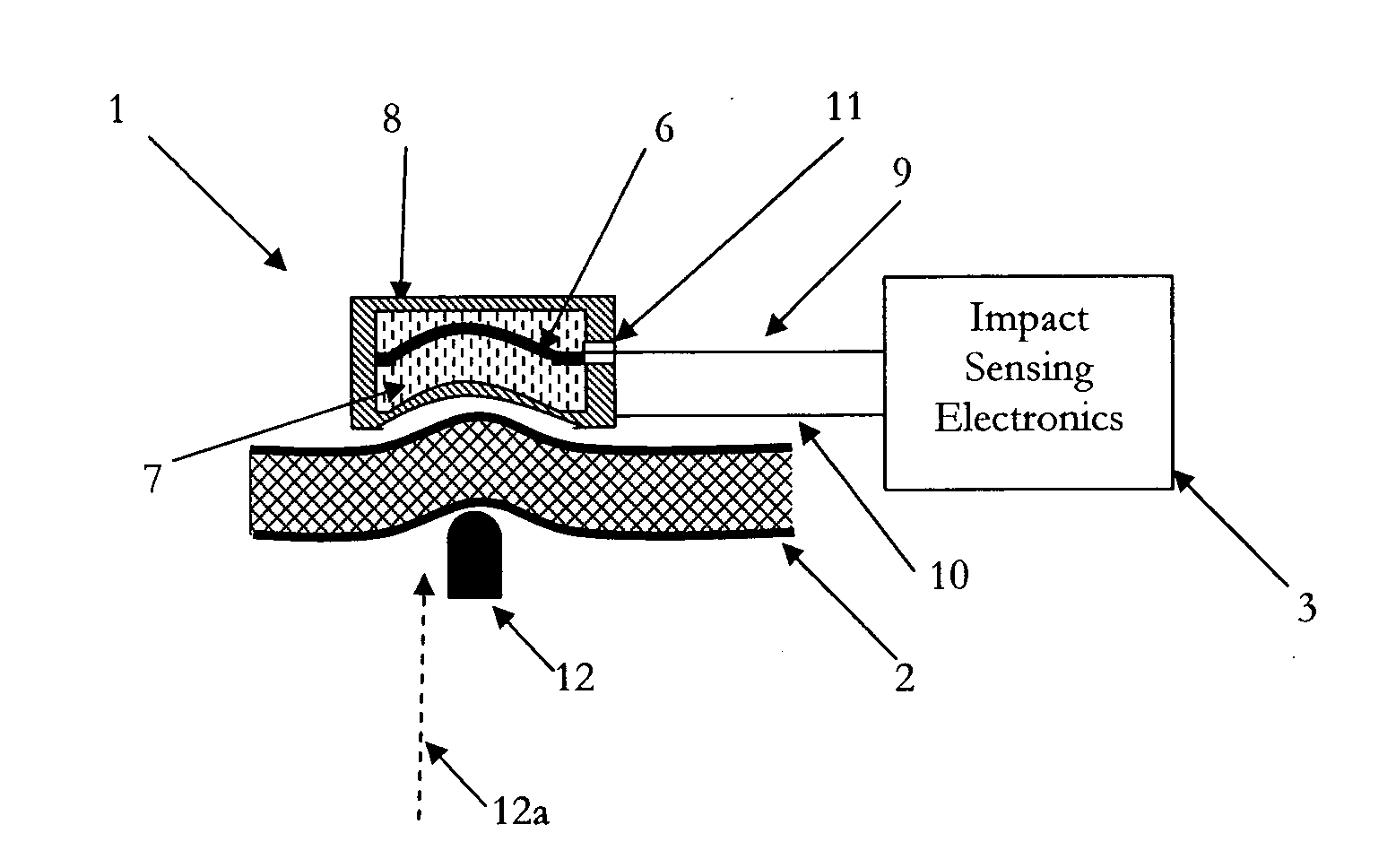
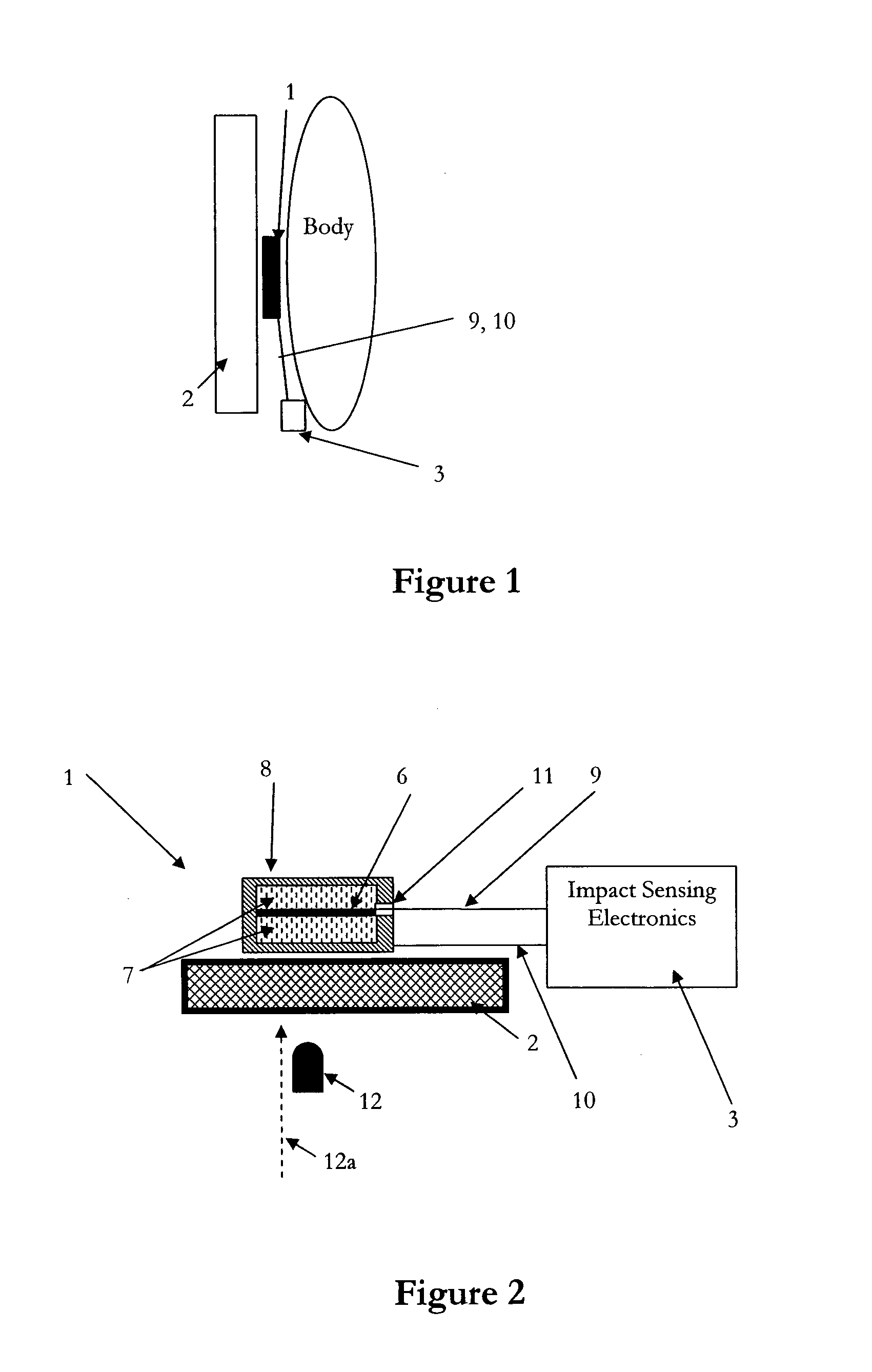
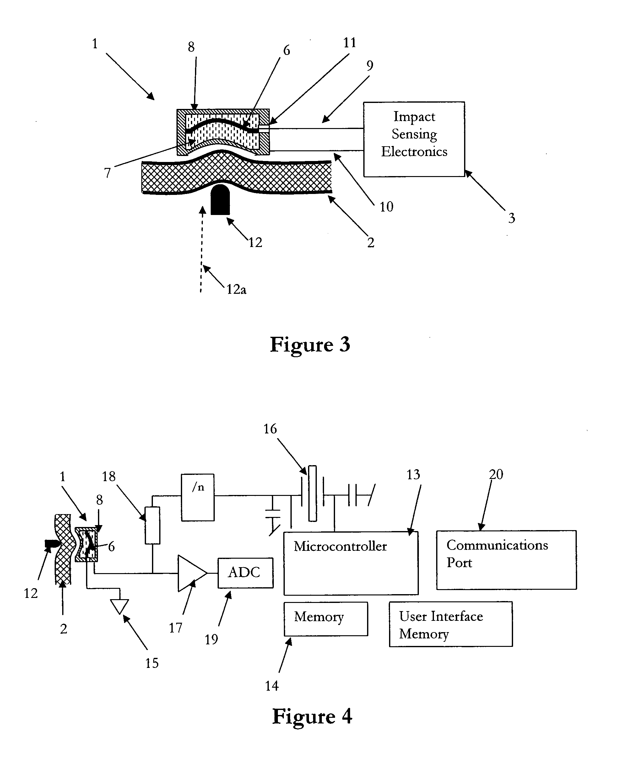
[0102]The detection and measurement of ballistic and / or non-ballistic impacts on a soldier's body for example would prove invaluable in the ability to increase the survivability of a soldier in a battle field situation. As an example, an impact detection system may facilitate a more rapid response by medics depending on the output generated from the detection system worn by a soldier as a result of an impact being detected.

[0103]The impact detection system of the present invention can be used on various types of impact surfaces such as body armour including a bullet proof vest, battle fatigues, a uniform, a body harness or strap, helmet or other garments designed for the body including underwear. Alternatively, the system can be used to detect impacts on other types of composite materials such as those found on an aircraft fuselage, boat hull or armour on a tank for example. These impacts can be of a ballistic or non-ballistic nature. The system provides a means of sensing, monitori...


PUM

PropertyMeasurementUnit
capacitanceaaaaaaaaaa
compressible non-conductiveaaaaaaaaaa
output resistanceaaaaaaaaaa

Abstract

An impact detection system provides a means of sensing, monitoring and recording impact events on an impact surface using at least one sensor that is incorporated into the impact surface. The sensor(s) can be integral with, attached to or located behind various types of impact surface including various types of garments that can be worn by an individual or on composite materials such as an aircraft fuselage for example. The impact detection system includes a portable impact detection device electrically connected to the sensor(s) and is used to detect ballistic or non-ballistic type impacts on the impact surface. The portable impact detection device processes the impact data detected by the sensor(s) and stores the data for analysis at a later time or outputs the data to a third party system for review and / or analysis.

Description

FIELD OF INVENTION[0001]The present invention relates to an impact detection system. In particular, although not exclusively, the impact detection system is capable of measuring a number of ballistic or non-ballistic type features, such as absorption energy for example, as a result of an impact on a body.BACKGROUND TO THE INVENTION[0002]A number of systems have been used in the past to detect and / or monitor the effects of an impact from an object, for example a projectile on a body. In a laboratory environment plastina clay has typically been used when trialling or testing the ballistic type effects of an impact from a projectile, such as a bullet for example, on a body whereby the plastina clay simulates body composition. Using this type of system it is not possible to measure the actual back face velocity of an armour plate for example that is placed in front of the plastina clay. Therefore, measurements relating to the impact of the projectile on the body are inferred by indirect...

Claims


Application Information

Patent Timeline
Patent Type & Authority Applications(United States)
IPC IPC(8): G01L5/00A41D13/015
CPCG01P15/0891F41H1/02F41J5/056A42B3/046G01L5/0052A41H1/02G01P15/125G01P1/127
Inventor RUSSELL, BRIAN KEITHMALLINSON, PAUL BENJAMINKENT, STEPHENSOLOMON, MICHAEL CHRISTOPHER
Owner ZEPHYR TECH CORP
Learn More