
Apparatus and method for transporting products, having a linear drive mechanism

Active Publication Date: 2010-04-08
SYNTEGON TECHNOLOGY GMBH
View PDF8 Cites 59 Cited by
  • Summary
  • Abstract
  • Description
  • Claims
  • Application Information

AI Technical Summary

Benefits of technology

[0007]The apparatus according to the invention for transporting products, having the characteristics of claim 1, has the advantage over the prior art of making safe, gentle product handling possible and can be used for many different products without complicated resetting work. In particular, special complicated format parts dependent on the product do not have to be changed. Moreover, the apparatus of the invention requires little space and can be furnished relatively inexpensively. This is attained according to the invention in that the transporting apparatus has a linear drive mechanism, which includes a first and a second linear segment and which is not disposed in curved conveyor regions. According to the invention, the complicated embodiment of the linear drive mechanism in the curved region of a continuous conveyor system can thus be dispensed with. The apparatus of the invention includes the continuous conveyor system, so as to return individual conveyor elements from a second station (output station) to a first station (intake station). Moreover, by the embodiment according to the invention, a very small radius in the curved region of the conveyor system can be attained, resulting in a very compact construction. Since furthermore the curved regions of the continuous conveyor system are designed as driveless, the transporting apparatus of the invention can be furnished especially inexpensively. According to the invention, transporting of the individual conveyor elements in the curved conveyor region of the conveyor system is effected by pushing trailing conveyor elements and/or by pulling leading conveyor elements that carry trailing conveyor elements along with them.
[0008]Preferably, the curved conveyor regions of the conveyor system each include one continuous driveless element. With this driveless element, the conveyor eleme

Problems solved by technology

However, this requires many transfer points and results in a great structural length.

Method used


Image

  • Apparatus  and  method  for  transporting  products,  having a  linear drive  mechanism
  • Apparatus  and  method  for  transporting  products,  having a  linear drive  mechanism
  • Apparatus  and  method  for  transporting  products,  having a  linear drive  mechanism

Examples


Embodiment Construction

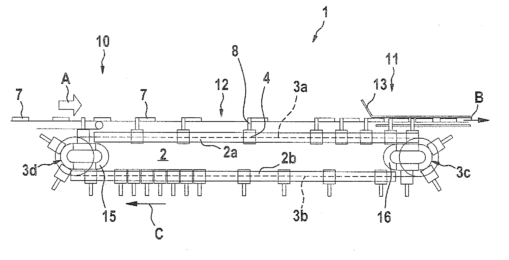
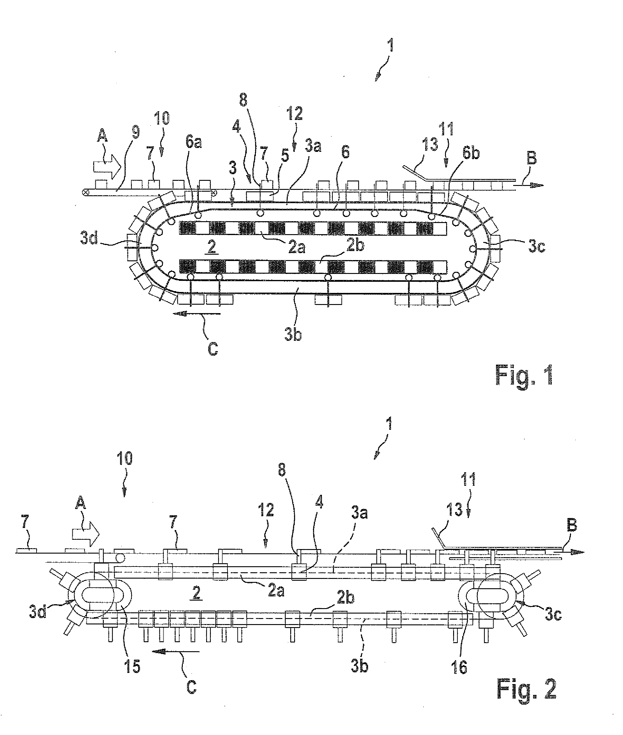
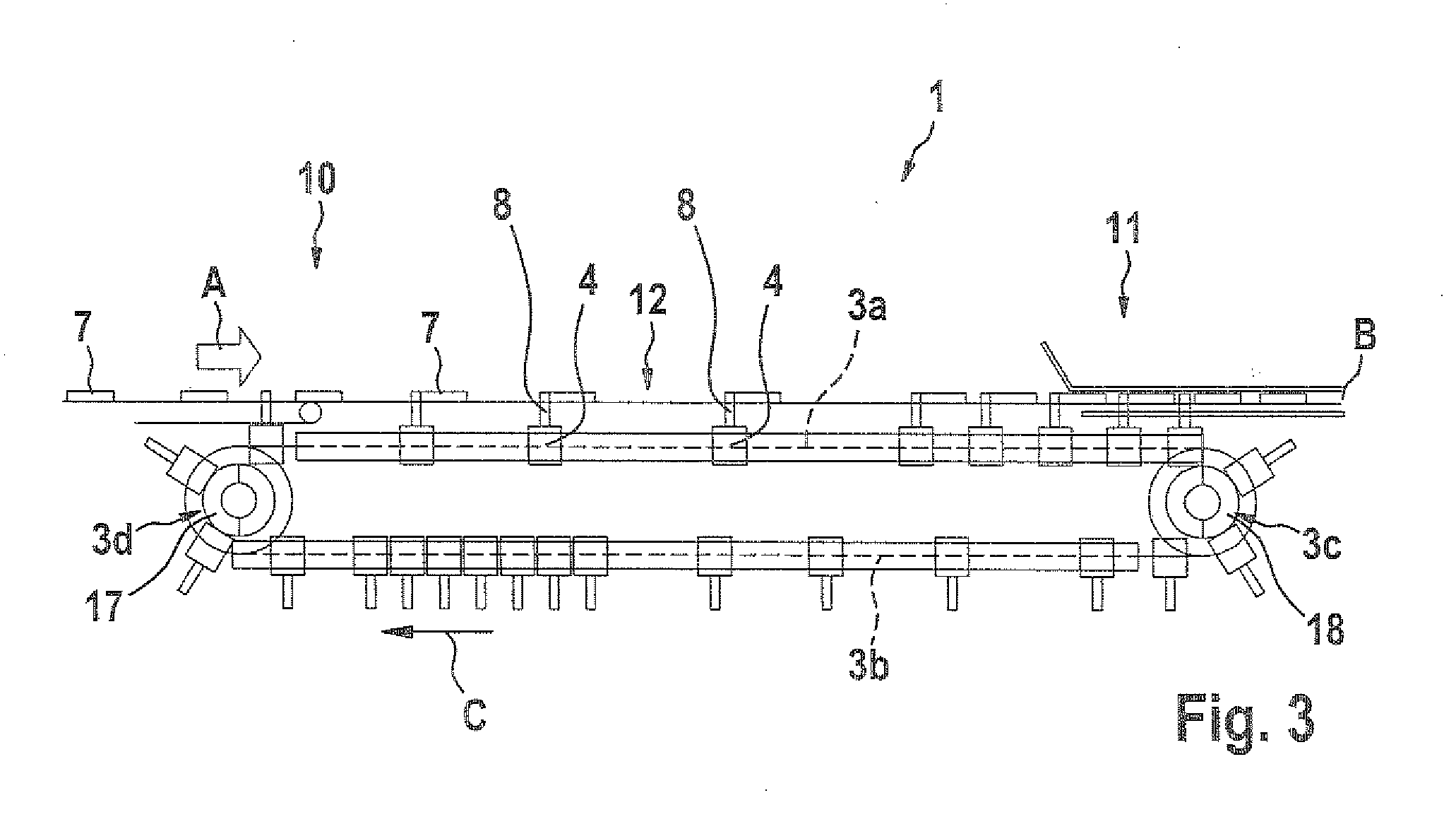
[0018]Below, in conjunction with FIG. 1, a transporting apparatus 1 in a first exemplary embodiment of the invention will be described in detail.

[0019]As can be seen from FIG. 1, the transporting apparatus 1 of the invention has a linear drive mechanism 2 with a first linear segment 2a and a second linear segment 2b. The two segments 2a, 2b are disposed parallel to one another and have the same length. The transporting apparatus 1 further includes a conveyor system 3, having a first and a second straight conveyor region 3a, 3b and a first and a second curved conveyor region 3c, 3d. The two curved conveyor regions 3c, 3d connect the two straight conveyor regions 3a, 3b. As a result, a continuous conveyor system is created on which a plurality of conveyor elements 4 can circulate. The conveyor elements 4 each include one permanent magnet 5 and one slide finger 8. As can be seen from FIG. 1, the slide finger 8 is guided on a continuous guide path 6, as a result of which it can vary its...


PUM


Abstract

The invention relates to a transporting apparatus for transporting products, which includes a linear drive mechanism, a continuous conveyor system, having two parallel straight conveyor regions and two curved conveyor regions each connecting one end of the straight conveyor regions, and a plurality of conveyor elements. The conveyor elements extend along the continuous conveyor system and convey the products to be conveyed along at least a portion of the conveyor system while being guided along a guide path. The linear drive mechanism includes a first linear segment and a second linear segment, which are disposed parallel to the straight conveyor regions. The curved conveyor regions of the conveyor system are advantageously embodied as driveless.

Description

CROSS-REFERENCE TO RELATED APPLICATION[0001]This application is based on German Patent Application 10 2008 040 204.4 filed Jul. 7, 2008.BACKGROUND OF THE INVENTION[0002]1. Field of the Invention[0003]The invention relates to an apparatus for transporting products with a linear drive mechanism between a first and a second station, and to a corresponding transporting method.[0004]2. Description of the Prior Art[0005]Apparatuses for transporting products are known in various embodiments from the prior art. Besides the known conveyor belts, recently linear drive mechanisms have increasingly been proposed as transporting apparatuses. From European Patent Disclosure EP 1 123 886 A1, for instance, one such apparatus with a linear drive mechanism is known, in which a continuous conveyor system is embodied as a linear motor, and individual conveyor elements each have a permanent magnet. The linear motor includes a plurality of coils, disposed side by side, which are disposed along the entire...

Claims


Application Information

Patent Timeline
IPC IPC(8): B65G19/22B65G47/00
CPCB65G19/02B65G54/02B65G47/28
Inventor WIPF, ALFREDLOECHT, HEINRICHSIERING, MARTIN
Owner SYNTEGON TECHNOLOGY GMBH
Learn More