Removable air intake structure for turbojet engine nacelle

a turbojet and air intake technology, applied in the direction of turbine/propulsion air intake, air transportation, power plant arrangement/mounting, etc., can solve the problems of over-all maintenance time-saving, and achieve the effect of removing and replacing the air intake structure and improving the outer aerodynamic line of the nacell

Active Publication Date: 2010-04-08
SAFRAN NACELLES
View PDF19 Cites 47 Cited by
  • Summary
  • Abstract
  • Description
  • Claims
  • Application Information

AI Technical Summary

Benefits of technology

[0010]Therefore, by incorporating the air intake lip into the outer panel so as to form a single removable part, a removal and partial replacement of the air intake structure are made possible and easier. Furthermore, removal made easier in this way also makes it possible to open the air intake structure in order to gain access to internal equipment without requiring considerable and complicated maneuvers nor requiring a long immobilization time. It should also be noted that there is then no longer a connection interface between the outer panel and the air intake lip, since only one possible longitudinal interface may exist in the case of a plurality of panels. This absence of interface perpendicular to an air flow makes it possible to improve the outer aerodynamic line of the nacelle.
[0011]It should also be noted that the present invention limits the size of the translatable outer panel substantially at the junction between the inner wall of the air intake and the fan casing. Therefore, the fan casing can still be fitted with its own access means.
[0012]Therefore, if maintenance is necessary only on the casing of the fan or on its junction with the inner wall of the air intake, it is not necessary to needlessly remove the outer wall of the air intake. The result of this is an overall maintenance time-saving, each section retaining an option of independent access.

Problems solved by technology

The result of this is an overall maintenance time-saving, each section retaining an option of independent access.

Method used


Image

  • Removable air intake structure for turbojet engine nacelle
  • Removable air intake structure for turbojet engine nacelle
  • Removable air intake structure for turbojet engine nacelle

Examples


Embodiment Construction

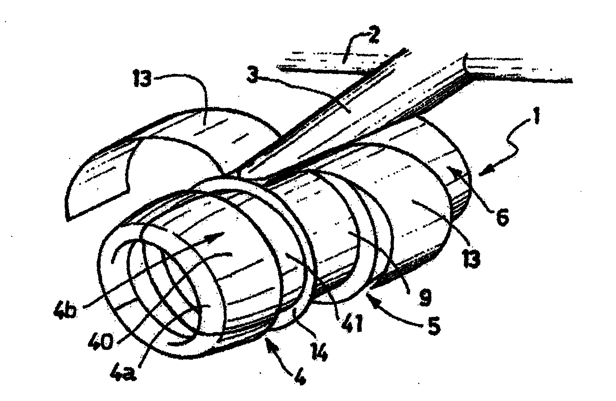
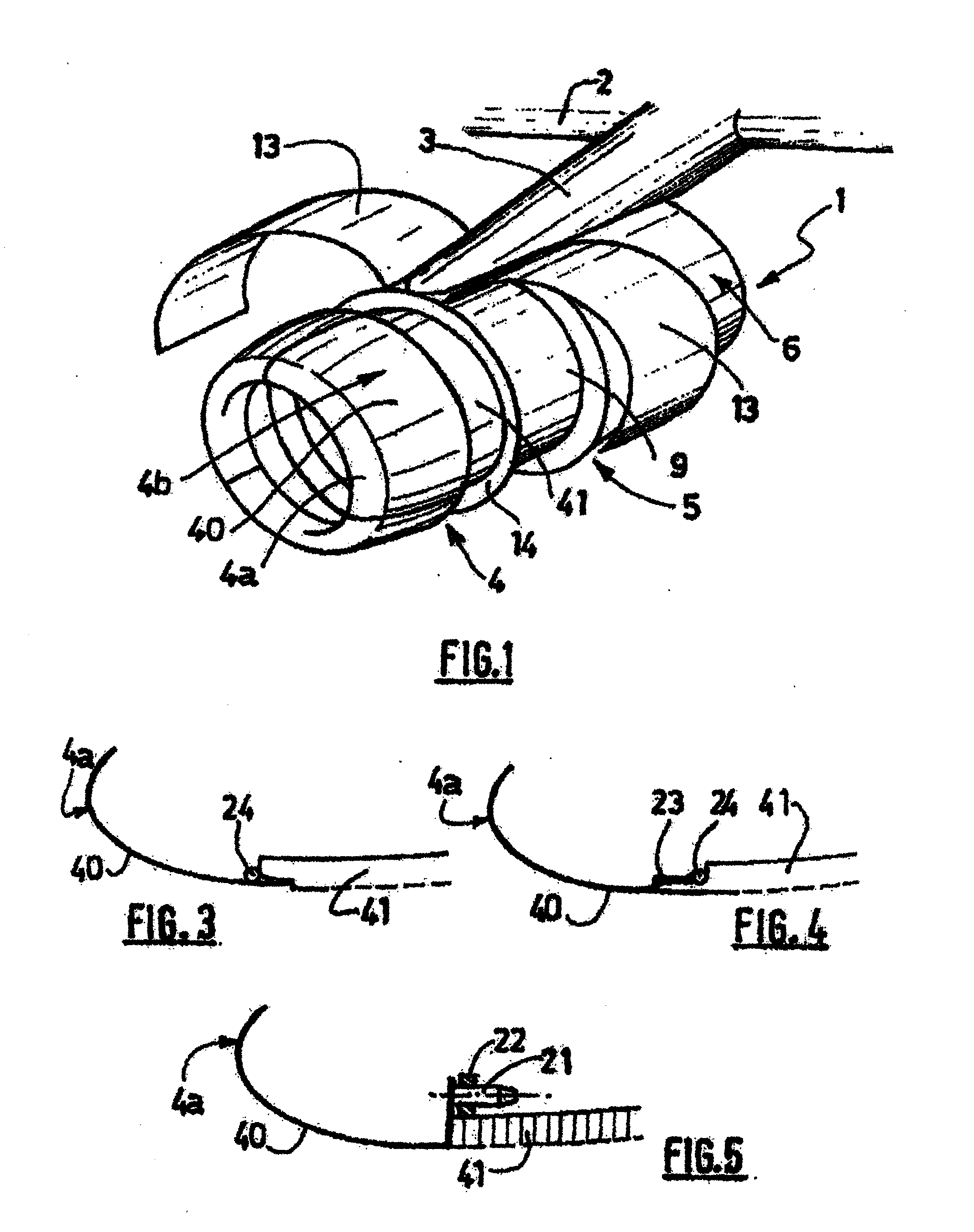
[0048]A nacelle 1 according to the invention as represented in FIG. 1 is a tubular housing for a turbojet (not visible) for which it serves to channel the air flows that it generates while defining inner and outer aerodynamic lines necessary to obtain optimal performance. It also houses various components necessary to the operation of the turbojet and ancillary systems such as a thrust reverser.

[0049]The nacelle 1 is designed to be attached to a fixed structure of an aircraft, such as a wing 2, by means of a pylon 3.

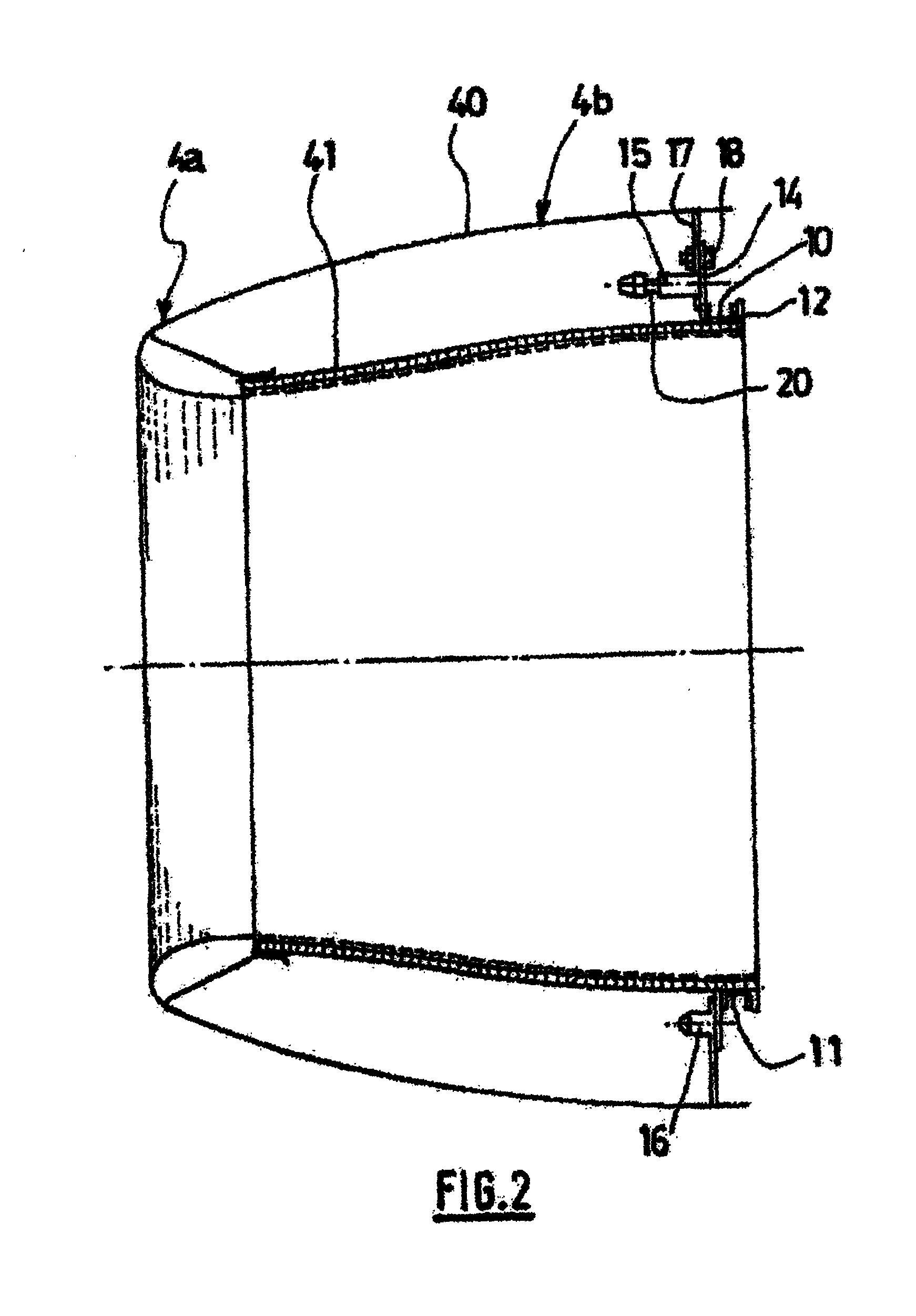
[0050]More precisely, the nacelle 1 has a structure comprising a front section forming an air intake 4, a middle section 5 surrounding a fan (not visible) of the turbojet, and a rear section 6 surrounding the turbojet and usually housing a thrust reverser system (not shown).

[0051]The air intake 4 is divided into two zones, namely on the one hand an intake lip 4a suitable for allowing for optimally gathering to the turbojet the air necessary to supply the fan and internal...


PUM


Abstract

The present invention relates to a nacelle (1) for a turbojet engine comprising an air intake structure (4) capable of ducting a flow of air towards a fan and a central structure (5) intended to surround the said fan and to which the air intake structure is attached, the central structure comprising a casing (9) intended to surround the fan and an external structure (13), characterized in that the air intake structure comprises, on the one hand, at least one internal panel (41) attached to the central structure via the casing and therewith forming a fixed structure and, on the other hand, at least one longitudinal external panel (40) attached removably to the fixed structure and incorporating an air intake lip (4a), the said external panel being removable between an operating position in which the external panel is aerodynamically continuous with the external structure of the central section and the air intake lip provides aerodynamic continuity with the internal panel of the air intake structure, and a maintenance position in which the external panel is separated from the external structure of the central section and the air intake lip is separated from the internal panel of the air intake structure.

Description

TECHNICAL FIELD OF THE INVENTION[0001]The present invention relates to a nacelle for a turbojet comprising an air intake structure capable of channeling an air flow toward a fan of the turbojet and a middle structure designed to surround said fan and to which the air intake structure is attached.BRIEF SUMMARY OF RELATED ART[0002]An aircraft is propelled by one or more propulsive assemblies comprising a turbojet housed in a tubular nacelle. Each propulsive assembly is attached to the aircraft by a pylon usually situated beneath a wing or on the fuselage.[0003]A nacelle usually has a structure comprising an air intake upstream of the engine, a middle section designed to surround a fan of the turbojet, a downstream section housing thrust reverser means and designed to surround the combustion chamber of the turbojet, and is usually terminated by an exhaust nozzle the outlet of which is situated downstream of the turbojet.[0004]The air intake comprises, on the one hand, an intake lip sui...

Claims


Application Information

Patent Timeline
Patent Type & Authority Applications(United States)
IPC IPC(8): B64D33/02B64C1/40
CPCB64D29/08B64D33/02B64D2033/0226F05D2240/14Y02T50/671F05D2230/64F02C7/04Y02T50/60
Inventor VAUCHEL, GUY BERNARDEPHERRE-IRIART, SERGE
Owner SAFRAN NACELLES
Why Eureka
Try Eureka