High Efficiency Piezoelectric Energy Harvester Having Spiral Structure

Inactive Publication Date: 2010-04-08
KOREA INST OF SCI & TECH
View PDF14 Cites 52 Cited by
  • Summary
  • Abstract
  • Description
  • Claims
  • Application Information

AI Technical Summary

Problems solved by technology

However the cost is high to connect an electric wire in each sensor

Method used


Image

  • High Efficiency Piezoelectric Energy Harvester Having Spiral Structure
  • High Efficiency Piezoelectric Energy Harvester Having Spiral Structure
  • High Efficiency Piezoelectric Energy Harvester Having Spiral Structure

Examples


Embodiment Construction

[0012]A detailed description may be provided with reference to the accompanying drawings. One of ordinary skill in the art may realize that the following description is illustrative only and is not in any way limiting. Other embodiments of the present invention may readily suggest themselves to such skilled persons having the benefit of this disclosure.

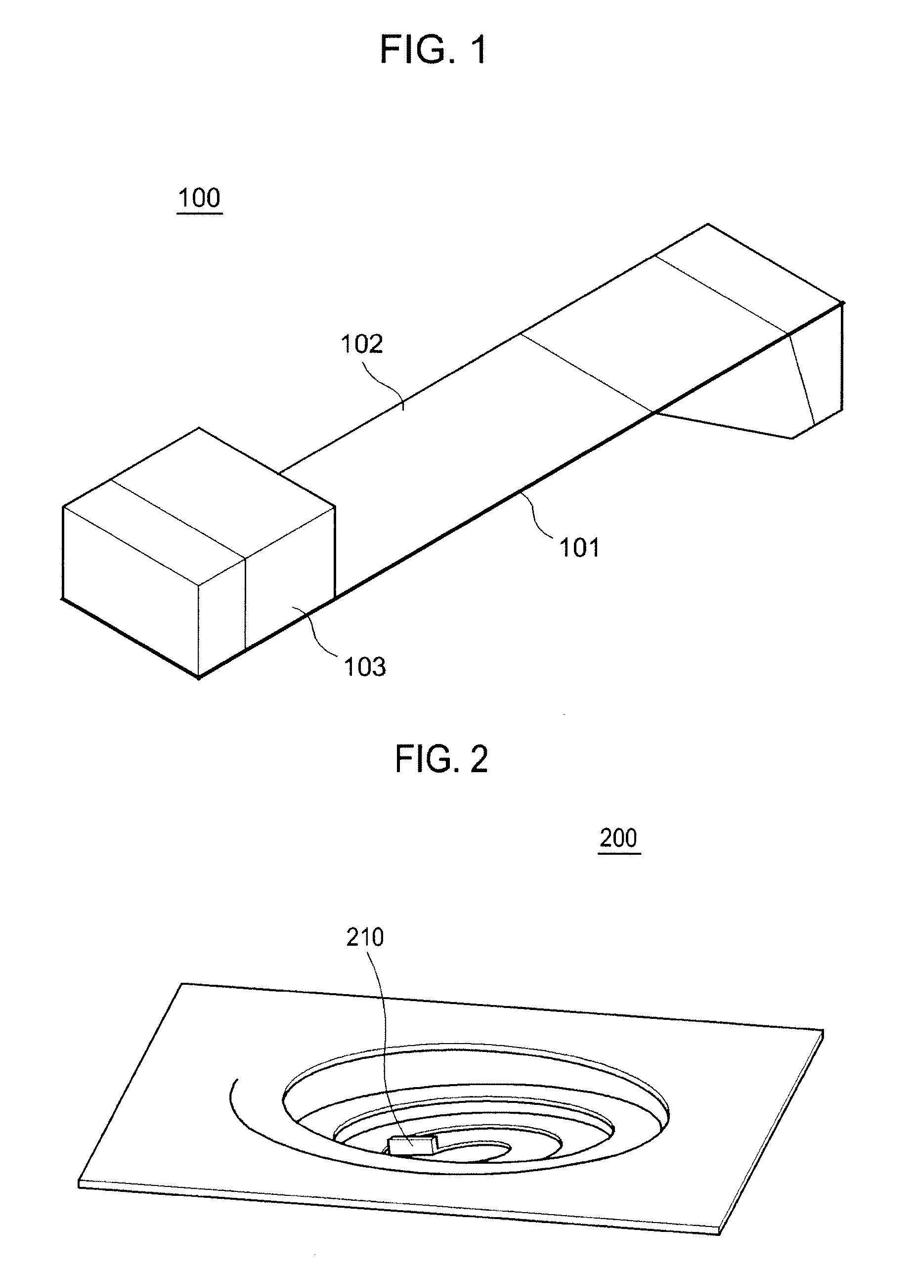
[0013]FIG. 1 is schematic diagram showing a cantilever type piezoelectric energy harvester. The cantilever type piezoelectric energy harvester 100 may include a substrate 101, a piezoelectric element 102 and a proof mass 103. The cantilever type piezoelectric energy harvester 100 may be fabricated to be small in size (micro) by using microelectromechanical systems (MEMS) for forming sensors, thin film rechargeable batteries and the piezoelectric energy harvesters on one chip. In this case, a natural frequency of the piezoelectric energy harvesting element may increase over hundreds of Hz. Because the frequency of an ambient vibration ...


PUM


Abstract

The present invention relates to a piezoelectric energy harvester having a high energy transformation efficiency and a low natural frequency. The piezoelectric energy harvester includes an elastic substrate having a spiral spring structure, a first electrode formed on the elastomeric substrate, a piezoelectric film formed on the first electrode and a second electrode formed on the piezoelectric film.

Description

[0001]The present application claims priority from Korean Patent Application No. 10-2008-0097375 filed on Oct. 2, 2008, the entire subject matter of which is incorporated herein by reference.BACKGROUND OF THE INVENTION[0002]1. Technical Field[0003]The present invention generally relates to piezoelectric energy harvesters, and more particularly to a piezoelectric energy harvester having a high efficiency for energy transformation and a low natural frequency.[0004]2. Background Art[0005]Piezoelectric energy harvesting is a process used to derive energy from ambient vibrations using piezoelectric materials. The ambient vibrations may be generated by a train, a vacuum pump, a mechanical motor, a car engine, a human's motion and so forth.[0006]Recently, a ubiquitous sensor network has been researched and developed for improving the quality of human life. In order to build a ubiquitous sensor network, it is necessary to install a plurality of sensors on a large area. However the cost is h...

Claims


Application Information

Patent Timeline
IPC IPC(8): H02N2/18
CPCH01L41/1136H10N30/306H03H9/24H03H3/08
Inventor YOON, SEOK-JINSONG, HYUN CHEOLKANG, CHONG YUNKIM, JIN SANG
Owner KOREA INST OF SCI & TECH
Why Eureka
Try Eureka