
Multiple color multi-functional light bar

a multi-functional, light bar technology, applied in the field of light bars, can solve the problems of difficult installation of multiple light bars and high cost of using multiple light bars, and achieve the effects of less complex manufacturing, less cost, and small siz

Inactive Publication Date: 2010-04-08
BROOKING INDS +1
View PDF26 Cites 24 Cited by
  • Summary
  • Abstract
  • Description
  • Claims
  • Application Information

AI Technical Summary

Benefits of technology

This patent describes an advantage for emergency vehicles: they can have one powerful light bar that shows different colored lights, rather than several separate ones that only work on one color or cannot change at all. This makes it cheaper and easier to install because there's no extra cost for every new feature. It also means that the car has fewer parts and works better overall.

Problems solved by technology

The technical problem addressed in this patent text relates to improving the visibility of emergency and legal vehicles during traffic controls and accidents. Current light bars have limitations in their ability to produce multiple colors and patterns, leading to increased expense and difficulty in installation. There is a need for a light bar that can display multiple colors and patterns simultaneously through a single optical lens, making them small and efficient in terms of cost and complexities involved in production.

Method used


Image

  • Multiple color multi-functional light bar
  • Multiple color multi-functional light bar
  • Multiple color multi-functional light bar

Examples


Embodiment Construction

[0032]In the following detailed description, reference is made to the accompanying drawings that form a part hereof, and in which is shown by way of illustration, specific embodiments in which the invention may be practiced. These embodiments are described in sufficient detail to enable those skilled in the art to practice the invention and like numerals represent like details in the various figures. Also, it is to be understood that other embodiments may be utilized and that process or other changes may be made without departing from the scope of the present invention. The following detailed description is, thus, not to be taken in a limiting sense.

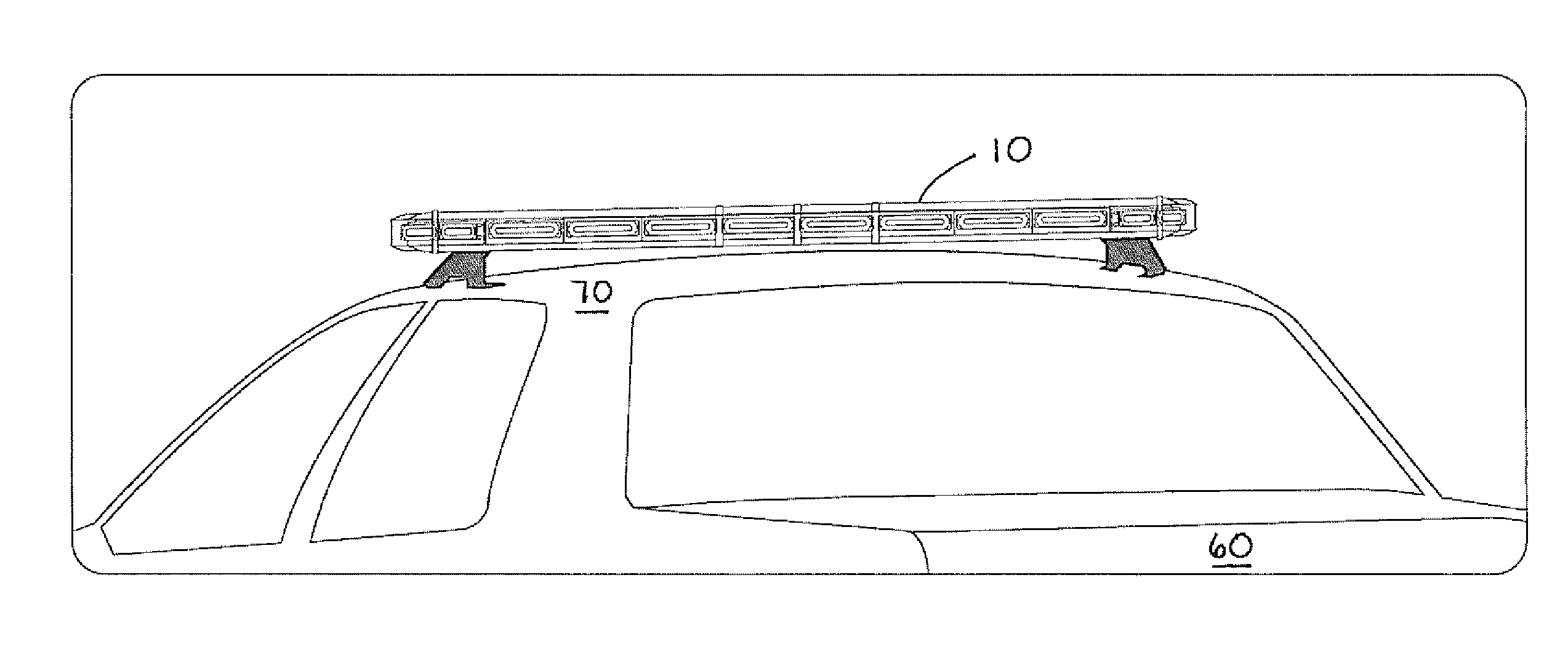
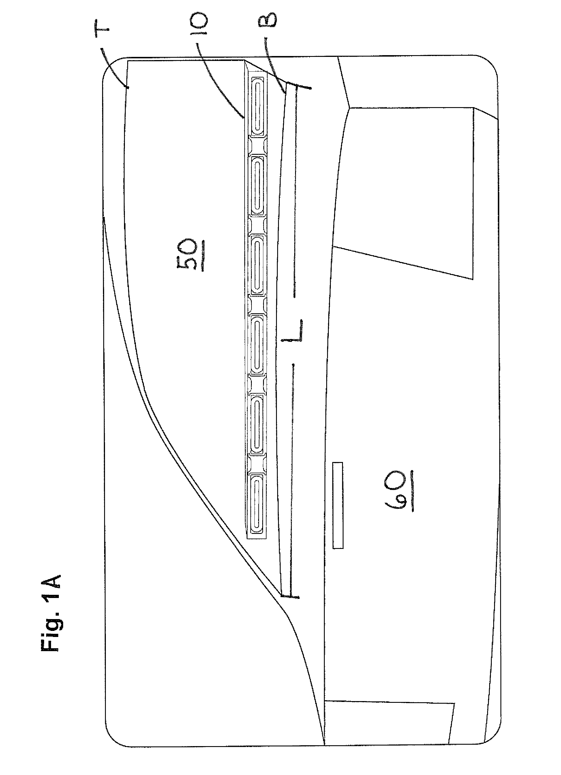
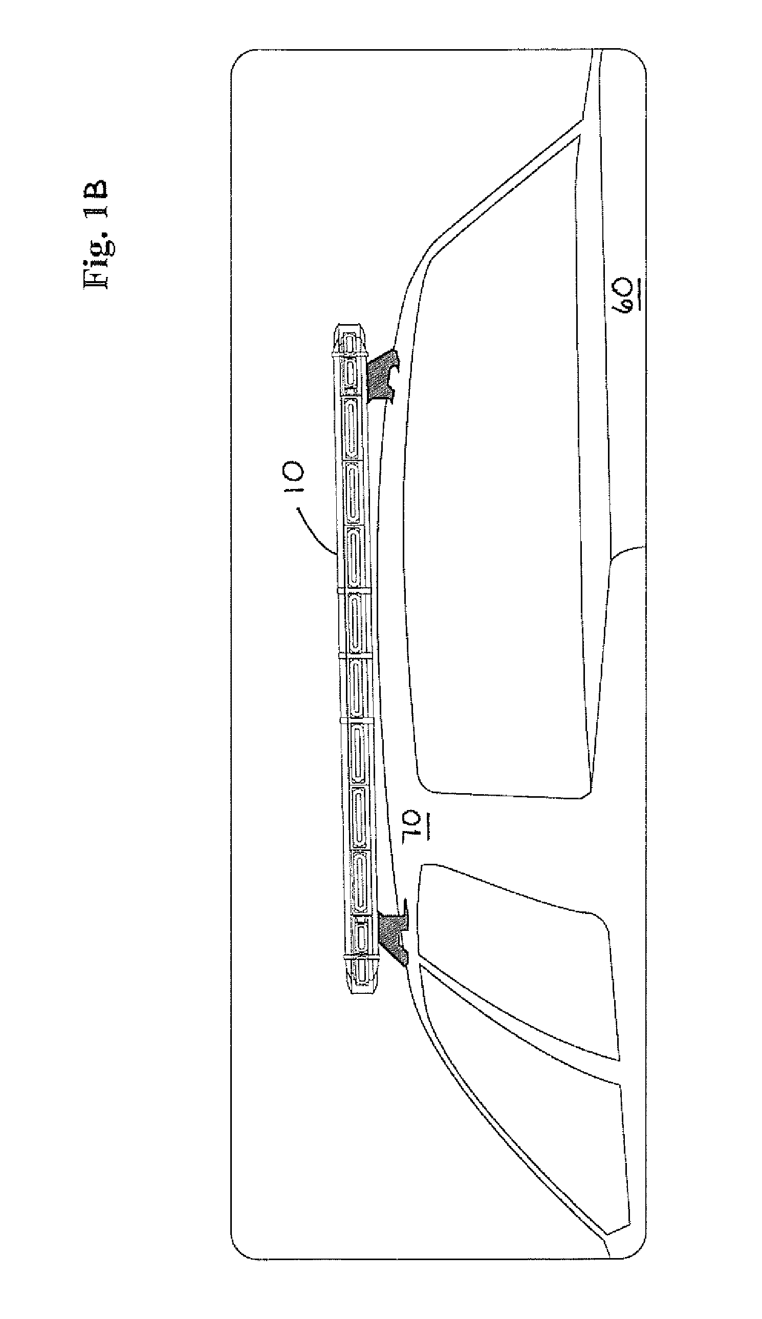
[0033]As best perhaps best illustrated in FIGS. 2A-2E, the present invention relates to a multiple color multi-functional light bar 10. Specifically, the light bar 10 includes a housing 20 with a base 30 and a cover 40. The base 30 and cover 40 of the housing 20 are designed to direct or project the light from the light bar 10 out of the...


PUM


Abstract

A multiple color multi-function light bar for a law enforcement vehicle, emergency vehicle, tow truck or the like. The light bar includes a plurality of light emitting diodes aligned in a single row. Each of the plurality of light emitting diodes are configured to emit two different colors of light through a single optical lens. Advantageously, the light bar is capable of producing a single color light pattern and a dual color light pattern based upon the particular emergency or traffic control situation encountered by an operator of the vehicle.

Description


Claims


Application Information

Patent Timeline
Owner BROOKING INDS
Learn More