Method of joining coiled sucker rod in the field

a technology of coiled sucker rods and welding methods, applied in the field of welding with hydrocarbon gas, can solve the problems of limited life and huge electric power requirements, and achieve the effect of small size and less cos

Inactive Publication Date: 2007-06-26
BOSTIK KAREL
View PDF10 Cites 6 Cited by
  • Summary
  • Abstract
  • Description
  • Claims
  • Application Information

AI Technical Summary

Benefits of technology

[0007]This special gas pressure welding method was developed for welding parts of a coiled sucker rod in the field. In this method the butted sections of the sucker rod are subjected to heat and pressure to form a weld. The method allows use of a light portable welding apparatus which is much smaller and less expensive than the heavy and cumbersome flash-butt welding machines used for welding of coiled sucker rod in the field at the present time. A critical aspect of the current method lies in eliminating any possible inclusions in the weld by displacing metal from the abutting faces of the welded rod ends into the narrow bulge created above the weld. To achieve this, the height of the bulge must be greater than one third of the diameter of the sucker rod being welded.

Problems solved by technology

Several methods of joining the continuous coiled sucker rod in the field were considered and experimented with (such as mechanical joints or explosive welding and hand welding with portable electrical welding machines etc.) and found impractical.
The biggest drawback of this method is its huge requirement of electric power, which has to be supplied from many large, heavy, and expensive batteries.
These batteries need to be recharged very often and their life is limited.

Method used


Image

  • Method of joining coiled sucker rod in the field
  • Method of joining coiled sucker rod in the field

Examples


Embodiment Construction

[0014]The preferred method will now be described with reference to FIGS. 1 through 5.

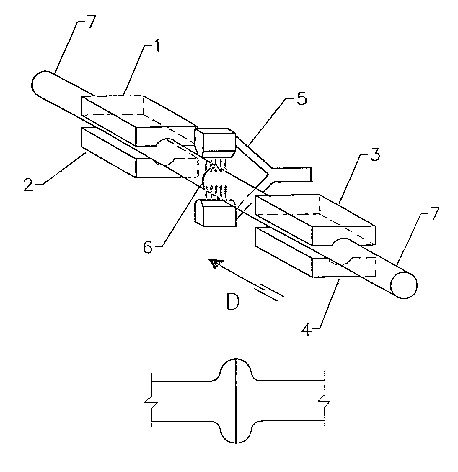
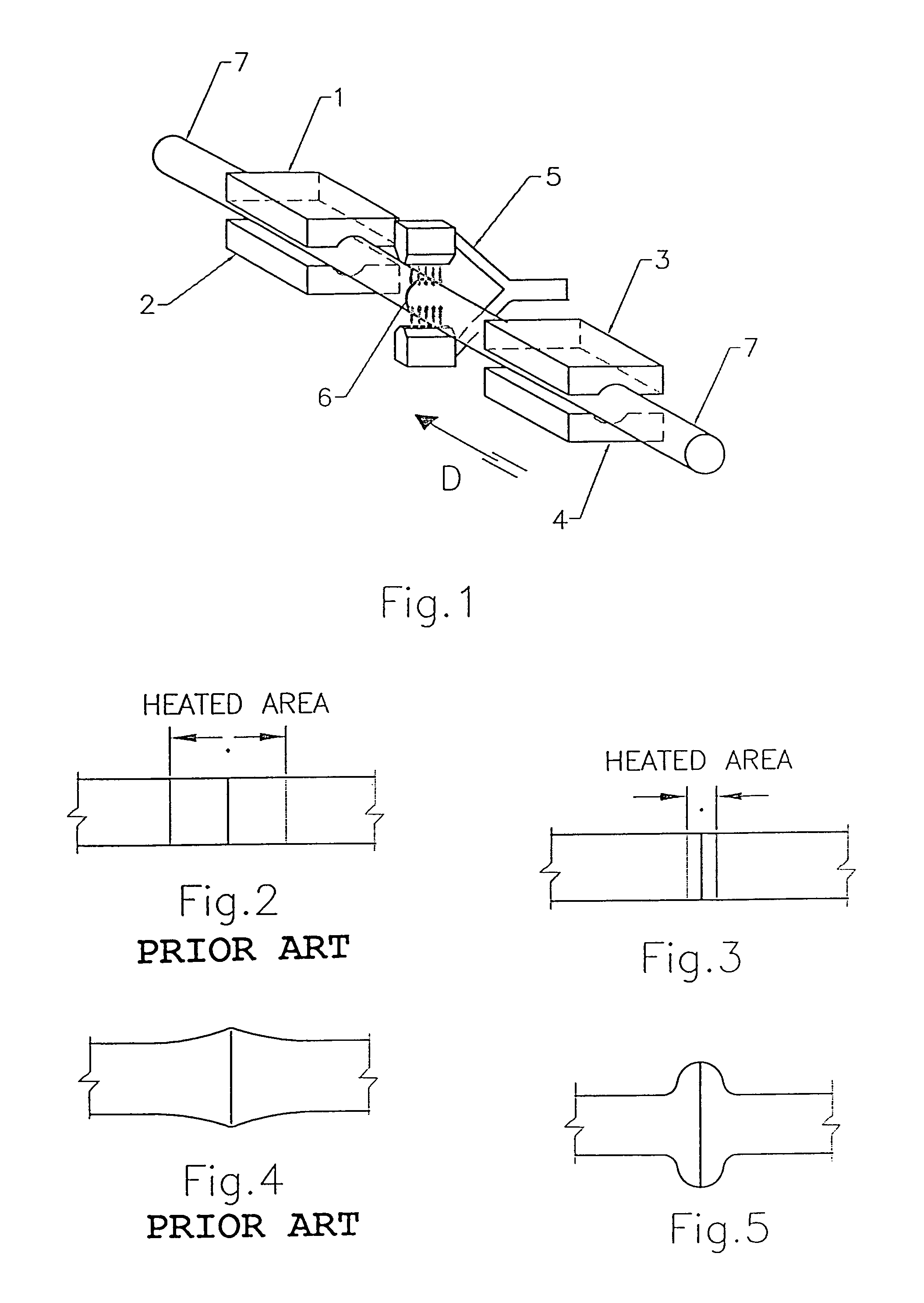
[0015]Referring to FIG. 1 two ends of coiled sucker rod 7 are held between stationery jaws 1, 2 and movable jaws 3, 4. Abutting ends 6 of rods 7 are in full contact, and multi-nozzle burner 5 is in position for heating rod ends 6. After the desired temperature is reached, movable jaws 3, 4 will start moving toward stationery jaws 1, 2 in direction D, compressing ends of rods 6, and welding two parts of rod 7 in to one rod.

[0016]FIG. 2 shows heated area of welded rods when welded using known methods, in contrast, FIG. 3 shows heated area of welded rods when welded using new method. FIG. 4 shows the bulge formed on a welded rod when welded using known methods, in contrast, FIG. 5 shows the bulge formed on welded rod when welded using new method.

[0017]The method, as will be hereinafter described, provides a reliable method of joining parts of a coiled sucker rod in the field without the need for expens...


PUM

PropertyMeasurementUnit
lengthaaaaaaaaaa
temperatureaaaaaaaaaa

Abstract

A method of joining coiled sucker rod in the field. In its most basic form, the method includes a first step of placing abutting ends of sucker rod in face to face relation. A second step involves positioning a gas burner in proximity to the abutting ends of sucker rod and heating the abutting ends with a hydrocarbon gas flame while applying axial pressure to force the abutting ends together. A third step involves continuing heating and applying pressure until a weld is formed with a bulge formed above the weld which is at least one third of the diameter of the welded rod. A fourth step involves keeping the pressure constant until the weld cools.

Description

FIELD OF THE INVENTION[0001]The present invention relates to welding with hydrocarbon gas.BACKGROUND OF THE INVENTION[0002]Continuous coiled sucker rod has been used in oil wells for the last 32 years. It is assembled in manufacturing plants from a number of pieces of steel rod supplied by a steel mill using a flash-butt welding machine. This is the most effective and reliable method of joining coiled sucker rod.[0003]During installation of a coiled sucker rod and servicing of wells with a coiled sucker rod the need for joining two pieces of a coiled sucker rod quite often arises. Several methods of joining the continuous coiled sucker rod in the field were considered and experimented with (such as mechanical joints or explosive welding and hand welding with portable electrical welding machines etc.) and found impractical.[0004]At present time the only reliable and practical method of joining a continuous coiled sucker rod in the field is electrical flash-butt welding with a truck o...

Claims


Application Information

Patent Timeline
Patent Type & Authority Patents(United States)
IPC IPC(8): B23K31/02B23K35/24B23K5/00B23K5/06B23K5/08B23K5/213B23K20/00
CPCB23K5/006B23K5/06B23K5/08B23K5/213B23K20/008B23K31/02B23K2201/06B23K2101/06
Inventor BOSTIK, KAREL
Owner BOSTIK KAREL
Why Eureka
Try Eureka