Regulator for fuel cell systems

a fuel cell and system technology, applied in the direction of fluid pressure control, process and machine control, instruments, etc., can solve the problems of fuel cell performance deterioration, inability to supply hydrogen gas, etc., to reduce the size and cost of the valve mechanism, and reduce the overall size of the regulator and its cost

Inactive Publication Date: 2005-03-17
AISAN IND CO LTD
View PDF9 Cites 7 Cited by
  • Summary
  • Abstract
  • Description
  • Claims
  • Application Information

AI Technical Summary

Benefits of technology

[0034] In the second aspect, further, the pressure regulating valve, in which the valve part is formed on the upper side and the shaft part is formed on the lower side, is disposed to be liftable in the hollow housing having a bottom; the fixed seat having a passage is arranged above the valve part; the spring to press the pressure regulating valve toward the sheet and the single O ring to provide sealing between the shaft part of the pressure regulating valve and the housing intervene in the housing; the housing is screwed into the housing accommodation chamber formed in the body of the regulator; and the two O rings, positioned upward and downward, intervene between the housing and the body. This configuration can contribute to reducing the size and cost of the valve mechanism having the pressure regulating chamber for pressure regulation as stated above, and coupled with the aforementioned size reduction of the diaphragms, makes it possible to reduce the overall size of the regulator and its cost.
[0035] Further according to the third aspect of the invention, even a regulator lacking the configuration described above is enabled to solve the problems of size and cost reduction, similarly to the above-described aspects of the invention, by serving to reduce the size and cost of the valve mechanism.

Problems solved by technology

Therefore, it is impossible to supply the hydrogen gas regulated to a higher pressure than the air pressure to allow for the possible pressure loss and accordingly to secure the hydrogen gas pressure required by the fuel cells, involving the risk of inviting a performance deterioration of the fuel cells.

Method used


Image

  • Regulator for fuel cell systems
  • Regulator for fuel cell systems
  • Regulator for fuel cell systems

Examples


Embodiment Construction

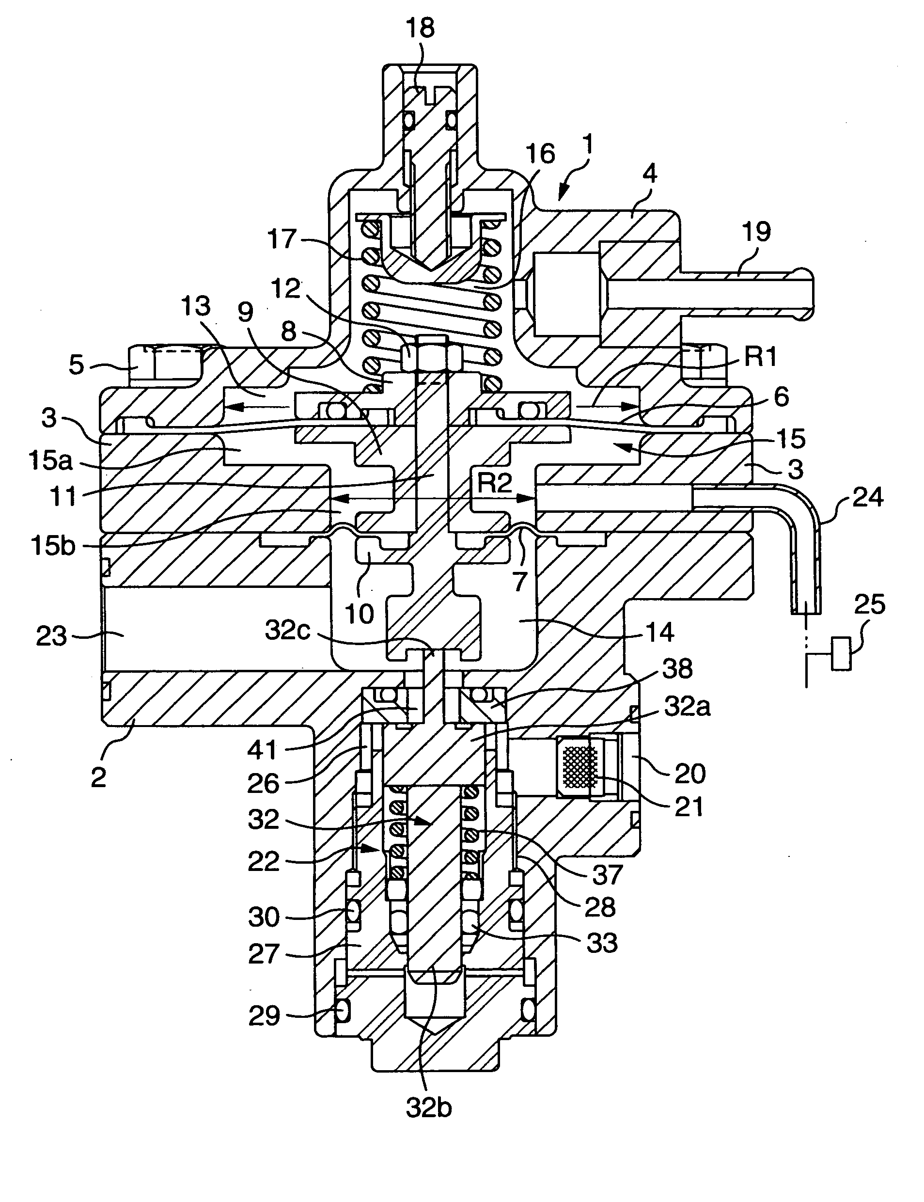
[0042]FIG. 1 shows a vertical sectional view of a regulator for fuel cell systems, which is a preferred embodiment of the invention.

[0043] Referring to FIG. 1, a regulator 1 has a lower body 2, an upper body 3 and a cover 4, and they are integrally linked with a bolt 5 and other elements.

[0044] Between the upper body 3 and the cover 4 arranged over this upper body 3, there is arranged a first diaphragm 6, which is the back pressure chamber side diaphragm, and the circumferential edge of the first diaphragm 6 is held between the upper body 3 and the cover 4.

[0045] Between the upper body 3 and the lower body 2 arranged underneath this upper body 3, there is arranged a second diaphragm 7, which is the pressure regulating chamber side diaphragm, and the circumferential edge of the second diaphragm 7 is held between the upper body 3 and the lower body 2. Therefore, the two diaphragms 6 and 7 constitute a double structure in which they face each other. Further, the diameter of the seco...


PUM

PropertyMeasurementUnit
pressureaaaaaaaaaa
pressureaaaaaaaaaa
areaaaaaaaaaaa

Abstract

To enable a regulator for fuel cell systems having a first diaphragm on the back pressure chamber side and a second diaphragm on the pressure regulating chamber side, wherein the pressure in the pressure regulating chamber is regulated with the back pressure in the back pressure chamber, to regulate the pressure with a pressure differing from the pressure in the back pressure chamber, the pressure in the pressure regulating chamber is regulated by actuating the pressure regulating valve with the shifting of the two diaphragms depending on the relationship between the two pressures, wherein the effective area of the first diaphragm and the effective area of the second diaphragm are differentiated.

Description

BACKGROUND OF THE INVENTION [0001] 1. Field of the Invention [0002] The present invention relates to a regulator for fuel cell systems, and more particularly to a regulator for regulating the pressure of fuel gas supplied to fuel cells in a fuel cell system comprising fuel cells which, supplied with fuel gas and oxidizer gas, generate electricity. [0003] 2. Description of the Related Art [0004] Known regulators for use in fuel cell systems as mentioned above include one having a structure shown in FIG. 3 (see for instance JP-A-2003-68334). This conventional regulator will be described below. [0005] In a body 101, two pressure regulating diaphragms 102 and 103 are arranged opposite each other with a space 104 provided between them, a space above one pressure regulating diaphragm 102 is formed into a back pressure chamber 105, and a space underneath the other pressure regulating diaphragm 103 is formed into a hydrogen gas passage 106 (pressure regulating chamber). [0006] The back pres...

Claims


Application Information

Patent Timeline
Patent Type & Authority Applications(United States)
IPC IPC(8): H01M8/04G05D16/06
CPCG05D16/0672Y10T137/7826
Inventor HASEGAWA, MASAKAZUSUZUKI, SHIGEHITO
Owner AISAN IND CO LTD
Why Eureka
Try Eureka