Data compression device and image reading device

a data compression and image technology, applied in the direction of digital output to print units, instruments, computing, etc., can solve the problems of increasing the compression time of image processing, not being able to know the size of data after compression, etc., and achieve the effect of reducing the compression time of image data

Inactive Publication Date: 2010-04-08
KYOCERA DOCUMENT SOLUTIONS INC
View PDF8 Cites 4 Cited by
  • Summary
  • Abstract
  • Description
  • Claims
  • Application Information

AI Technical Summary

Benefits of technology

[0010]It is an object of the present invention to provide a data compression device capable of reducing the compression time of image data and an image reading device that includes this data compression device.

Problems solved by technology

Also, the compression ratio of the image data varies depending on the content of the image data, so without compressing the data it is not possible to know the size of the data after compression.
In this case time is necessary for encoding setting after completion of execution of compression processing of a certain band until the start of compression processing of the next band, and this has the problem that the compression time of image processing is increased.

Method used


Image

  • Data compression device and image reading device
  • Data compression device and image reading device
  • Data compression device and image reading device

Examples


Embodiment Construction

[0017]The method of shortening the image data compression time in the data compression device is, for example, as follows.

[0018]FIG. 4 is a diagram for explaining a reference example of a method for shortening the image data compression time.

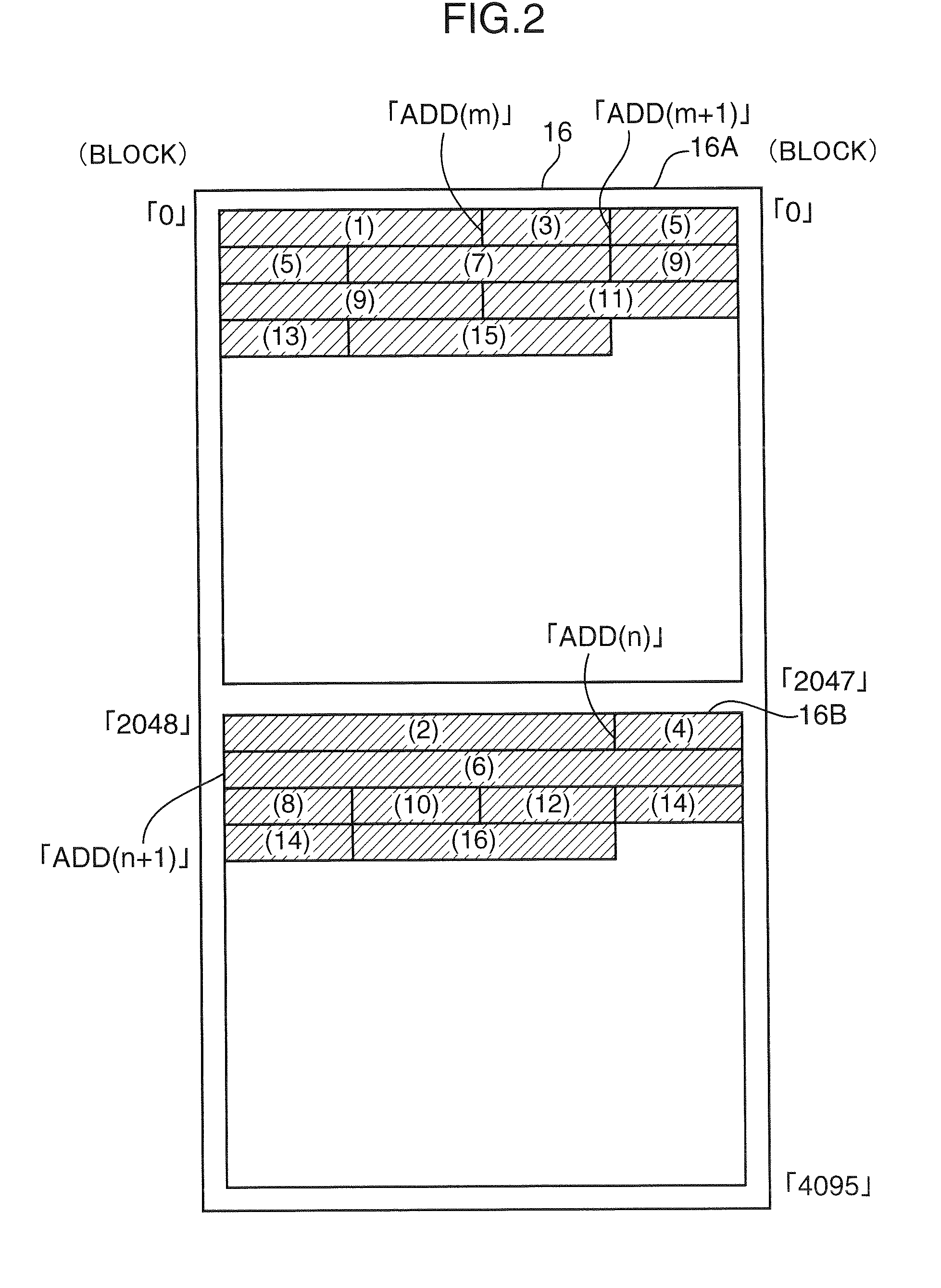
[0019]A plurality of storage areas 110 . . . is provided in advance in a page memory 100. Each storage area 110 . . . corresponds to a band, which is described later, and encoded data (1) to (14) corresponding to each band is stored in each storage area 110 . . . . Here, “band” is 1 unit representing a specific number of lines of the image in the sub scanning scan direction, as explained later.

[0020]As shown in FIG. 4, a plurality of storage areas 110 corresponding to each band is provided in the page memory 100, so the starting address in the page memory 100 where the encoded data of the next band should be stored is known even if the time for generating the encoded data of one band has not finished. However, according to this method the storag...


PUM


Abstract

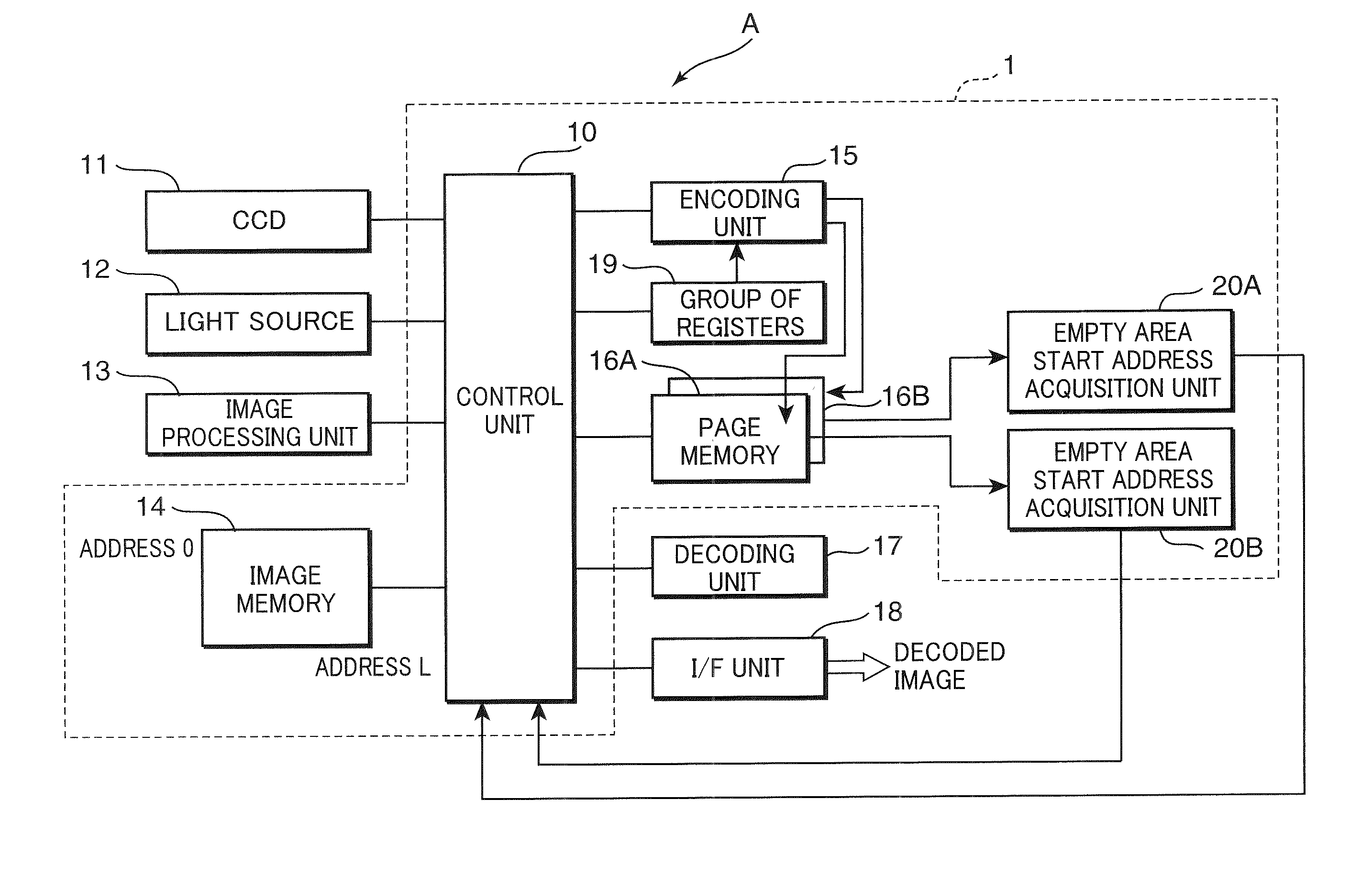
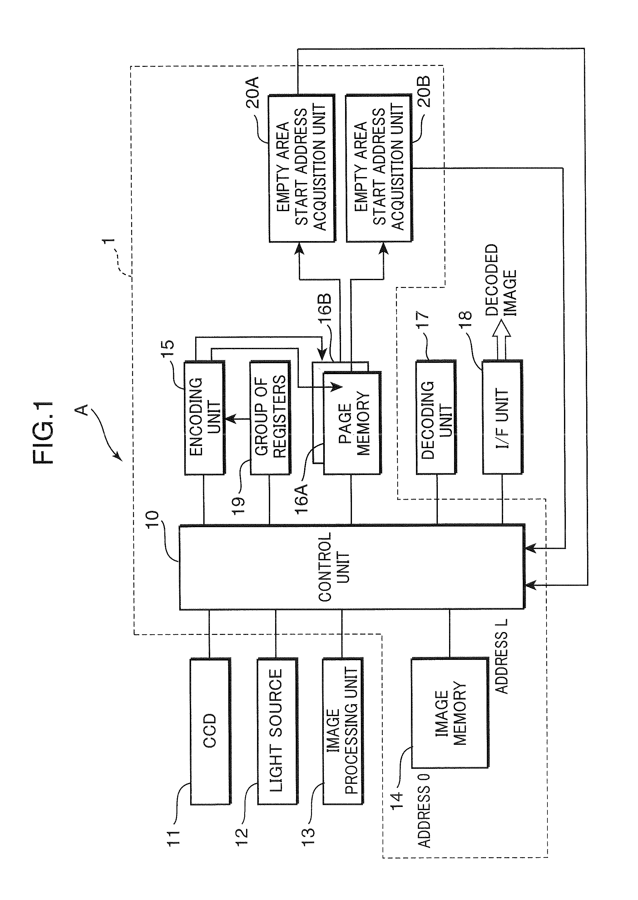
A data compression device includes an encoding unit that generates encoded data by compressing image data in units of a band. Encoded data storage units have addresses for storing encoded data for each band and a settings receipt unit receives start address settings in the storage units. A control unit stores the data in the storage units every time encoded data for each band is generated. A start address acquisition unit acquires the start address of an empty area where encoded data is not stored. The control unit sets the start address of an empty area in a storage unit different from the storage unit where the encoded data that is being generated is to be stored. The encoding unit then starts to generate encoded data for a next band, and stores the generated data in the storage unit indicated by the start address set in the setting receipt unit.

Description

BACKGROUND OF THE INVENTION[0001]1. Field of the Invention[0002]The present invention relates to a data compression device and an image reading device.[0003]2. Description of the Related Art[0004]Image reading devices such as facsimile machines, image scanners, copying machines, and so on include a data compression device that generates encoded data by compressing the image data to a specific compression ratio. Also, the compression ratio of the image data varies depending on the content of the image data, so without compressing the data it is not possible to know the size of the data after compression.[0005]Image processing devices that include this type of data compression device include a plurality of compressed page memories (hereafter referred to as page memory) (see Japanese Patent Application Publication No. 2000-261630). This type of image processing device is constituted so that the status of use of the plurality of page memories varies dynamically in accordance with the le...

Claims


Application Information

Patent Timeline
Patent Type & Authority Applications(United States)
IPC IPC(8): H04N1/04G06F12/00G06K9/36H03M7/30H04N1/41H04N19/00H04N19/423
CPCH04N1/41H04N1/40
Inventor BABA, MASAKI
Owner KYOCERA DOCUMENT SOLUTIONS INC
Why Eureka
Try Eureka