[0007] The object of this invention is to provide a method which will avoid these disadvantages of the known method and which will send preferably all the gas quantity available at
ambient pressure to the gas
recovery system.
[0008] This object is achieved according to this invention by compressing the gas directly from the pressure prevailing in the chamber, at least one additional compression stage being used when the pressure in the chamber falls below a limit level. According to this invention, gas is removed from the chamber until the pressure in the chamber reaches the
limit value of the
intake pressure. The
limit value of the
intake pressure is determined by the design of the compression stage because for each compressor there is a minimum
intake pressure up to which the compressor is able to compress the gas to the required pressure and below which compression is no longer possible. Since the chamber has been evacuated to the respective
limit pressure with one compression stage, according to this invention another compression stage is added. With this second compression stage, it is possible to remove the gas from the chamber at the lower pressure and compress it in the subsequent stage. Thus with the inventive method, the
pressure level prevailing in the chamber at any given time is utilized appropriately. Since a very high pressure prevails in the chamber mainly at the start of removal of the gas, this pressure often being only slightly below the pressure of the high-pressure container and dropping with removal of the gas but still being far above
atmospheric pressure and only slowly approaching the latter, therefore only the
pressure difference prevailing between the chamber and the high-pressure container at that moment need be overcome with the inventive method.
Compression time is shortened considerably because consequently now only a very small amount of the gas must overcome a great
pressure difference and the
energy demand required for compression is also drastically reduced—in comparison with compression from
atmospheric pressure. Compression starting from atmospheric pressure is necessary with the method previously customary in which the gas is depressurized into a gas buffer. The fact that this gas buffer is omitted in the inventive method is a great
advantage because the gas buffer takes up a large space due to the large volume of the gas under atmospheric pressure. This is advantageous not only in the case of tight spatial conditions but also the space savings have an economically advantageous effect. Furthermore, the inventive method is characterized by a low
investment cost.
[0012] In an embodiment of this invention, the individual compression stages have different compression capacities. It is particularly advantageous here that the gas in the highest compression stage (n-th stage) with which this gas is compressed with the highest compression capacity of the individual compression stages before any other additional stage, i.e., (n−1)-th stage is added. This may be accomplished through appropriate
dimensioning of this compressor or through a parallel circuit of multiple compressors. A high compression output in the highest compression stage greatly reduces the time required for compression because in particular at the beginning of withdrawal large quantities of gas are generated.
[0014] It is also particularly advantageous that the inventive method is used for
recovery nitrogen,
argon or
helium and mixtures thereof. In the heat treatment, quenching is often performed with
nitrogen. Therefore, the inventive method has been designed for recovery of
nitrogen with particular advantages. However, recovery of other quenching gases, e.g.,
argon or
helium as well as mixtures of nitrogen,
argon and
helium is also possible to
advantage. Since the inventive method is characterized by a low
investment cost, it also permits economical recovery of relatively inexpensive gases such as nitrogen. When expensive gases or gas mixtures which have previously also been sent for recovery are used for quenching, the inventive method makes the recovery much less expensive.
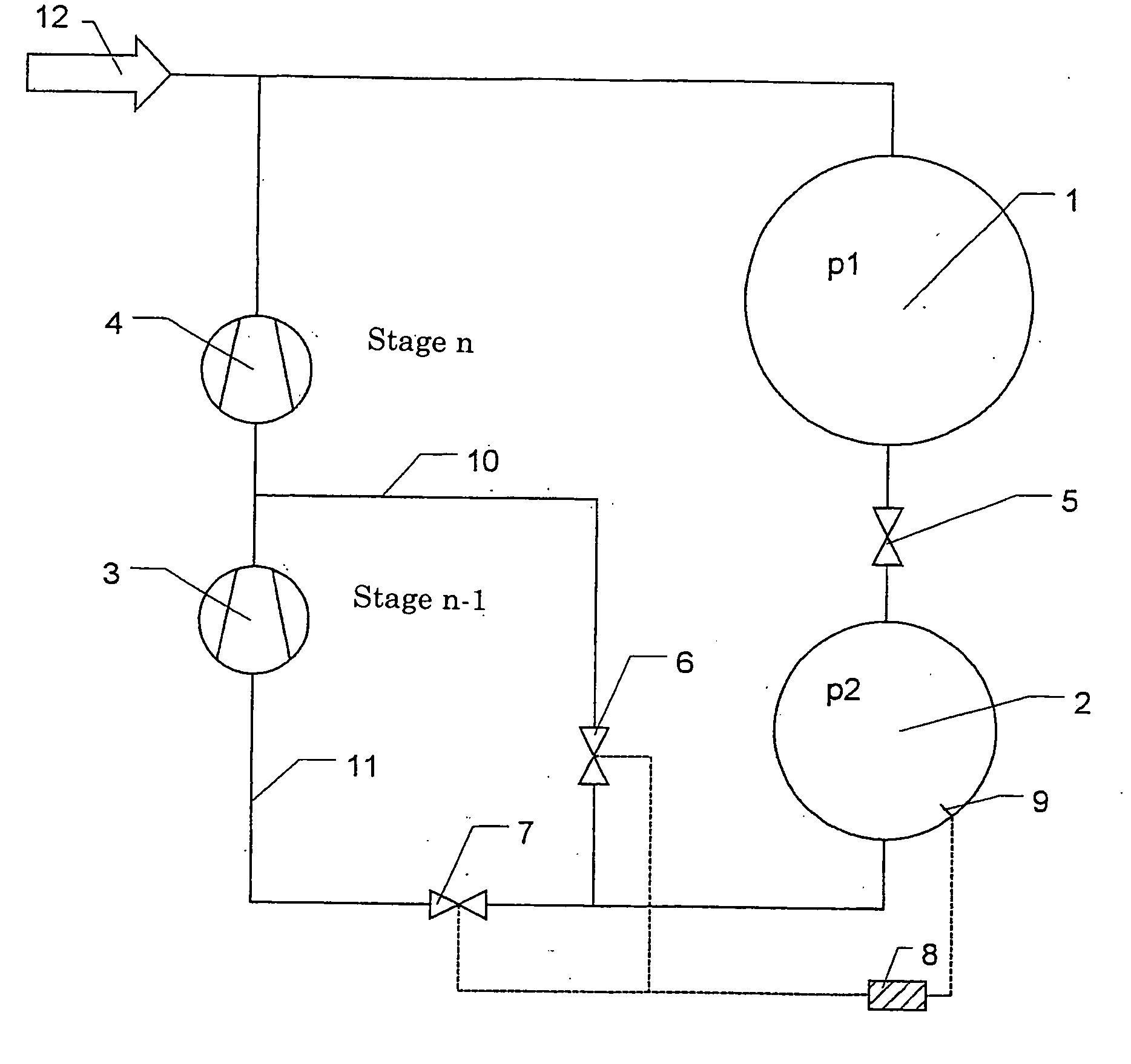
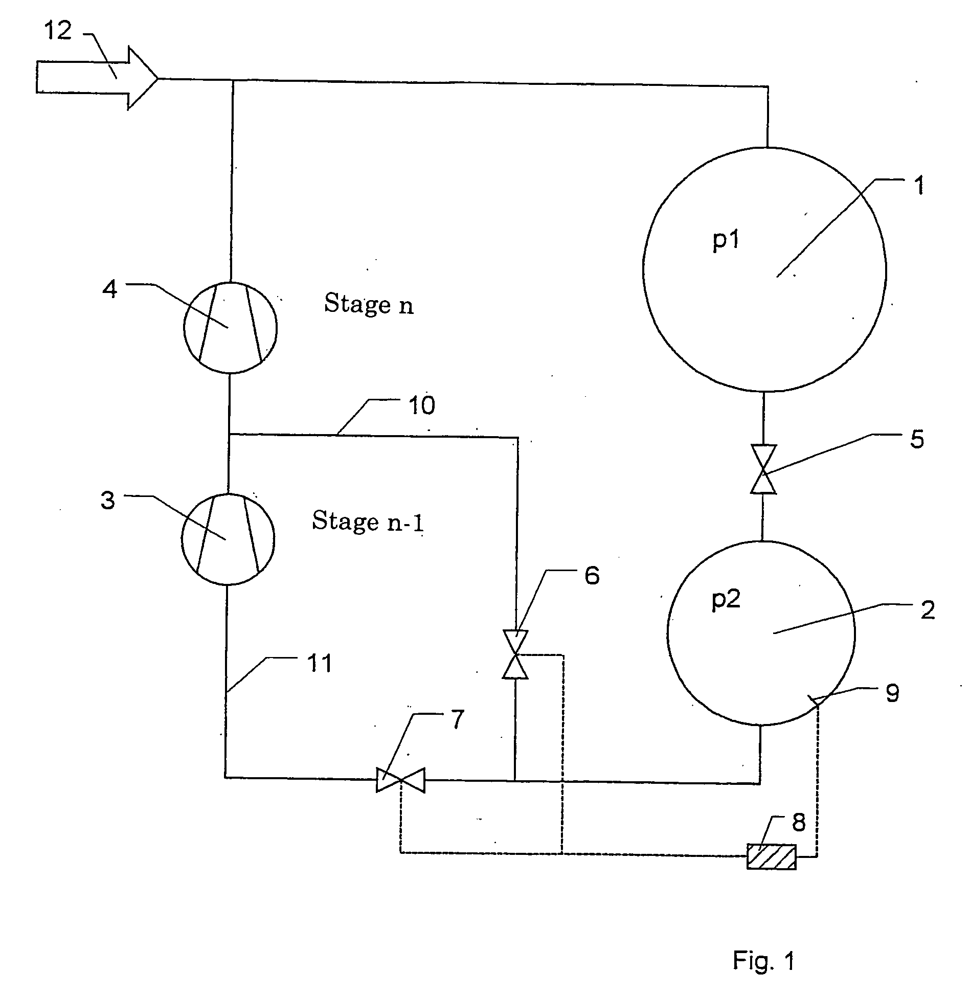
[0015] This object is achieved for this device according to this invention by the fact that the chamber communicates with at least two compressors that are connected in series and form at least two compression stages or with each compression stage of a
multistage compressor communicates via connecting lines directly without an intermediate reservoir, whereby the connecting lines include opening and closing
overcurrent regulators or
cut-off elements which are connected to a switch unit that controls the
cut-off elements and whereby the highest compression stage (n-th stage) of the compressors connected in series or of the
multistage compressor communicates with the high-pressure container. With the inventive device it is thus possible in a multistage compressor to separately supply the individual compression stage responsible for different pressure ranges or the different compressors which form a multistage compressor through a series connection. It is thus possible to use the respective compression stage according to its design with respect to the
pressure range. The lines lead between the stages according to this invention and carry the gas to the next higher compression stages. The gas does not reach them until after compression in this stage. If there is no higher stage, the gas enters the high-pressure container.
Overcurrent regulator or
cut-off elements
cut off the lines leading to the lower compression stages and cause the gas to be sent to higher compression stages.
Overcurrent regulators are mechanical regulators which determine the pressure prevailing upstream from the valve and open or close according to this pressure. However, the switching unit assumes control of the cut-off elements. The switching unit preferably includes a
pressure sensor for determining the pressure in the chamber. If the pressure in the chamber drops below the specific
limit value for the particular compression stage, the
overcurrent regulators then open and close in such a way and / or the switching unit sets the cut-off elements in such a way that another lower compression stage assumes the role of compression in the
pressure range below that of the previous compression stage, and the previous stage recompresses the gas coming from the lower stage. On evacuation of the chamber, consequently the highest compression stage (n-th stage) performs the compression first, then the switch unit switches the next lower compression stage ((n−1)-th stage) and so far until all the compression stages are in operation. Consequently with the inventive device it is not necessary to depressurize the gas of the chamber into a gas buffer and to use all the stages according to their sequence for the total quantity of gas. Saving by eliminating the gas buffer means enormous savings in terms of space.
[0017] Advantageously one or more compression stages include multiple compressors connected in parallel because the compression performance of
one stage is increased by the parallel switching. However, the compression performance of a compression stage is also increased through appropriate
dimensioning.

