
Hybrid internal combustion engine and air motor system and method

a hybrid internal combustion engine and air motor technology, applied in machines/engines, process and machine control, vehicle sub-unit features, etc., can solve the problems of subsequent deceleration waste of energy, and achieve the effect of maximizing air motor efficiency, and maximizing air compressor efficiency

Active Publication Date: 2010-04-08
VOLVO LASTVAGNAR AB
View PDF1 Cites 31 Cited by
  • Summary
  • Abstract
  • Description
  • Claims
  • Application Information

AI Technical Summary

Benefits of technology

[0002]Typical city driving patterns for vehicles include many accelerations and decelerations. A significant portion of fuel energy is spent in accelerating the vehicle. This energy is wasted during subsequent decelerations. A pneumatic hybrid engine captures and reuses some of this energy. During braking, the engine can utilize the braking energy to work as a compressor, pumping compressed air into an on-board tank. Later, during acceleration, the engine can be powered by the stored compressed air with or without burning diesel fuel to get up to speed or until the compressed air is depleted. The additional work performed by the compressed air permits a reduction in the quantity of fuel needed to achieve the required engine power. In this way, the engine efficiency can be increased, and the vehicle fuel economy can be improved.
[0042]In accordance with another aspect of the present invention, a hybrid internal combustion engine and air motor system is provided and comprises at least one chamber having a drivable member and at least one intake valve and at least one exhaust valve, and a reservoir connected to the chamber through at least one of the intake valve and the exhaust valve. The system further comprises a computer configured to calculate air motor efficiency (ηAM) during an air motor mode of operation and select an intake and exhaust valve opening and closing timing sequence for maximizing air motor efficiency so that(ηAM)(ValveTiming)=0and2(ηAM)2(ValveTiming)<0.

Problems solved by technology

This energy is wasted during subsequent decelerations.

Method used


Image

  • Hybrid internal combustion engine and air motor system and method
  • Hybrid internal combustion engine and air motor system and method
  • Hybrid internal combustion engine and air motor system and method

Examples


Embodiment Construction

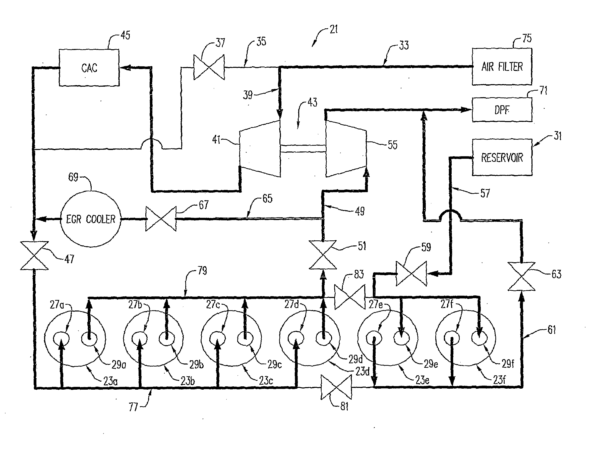
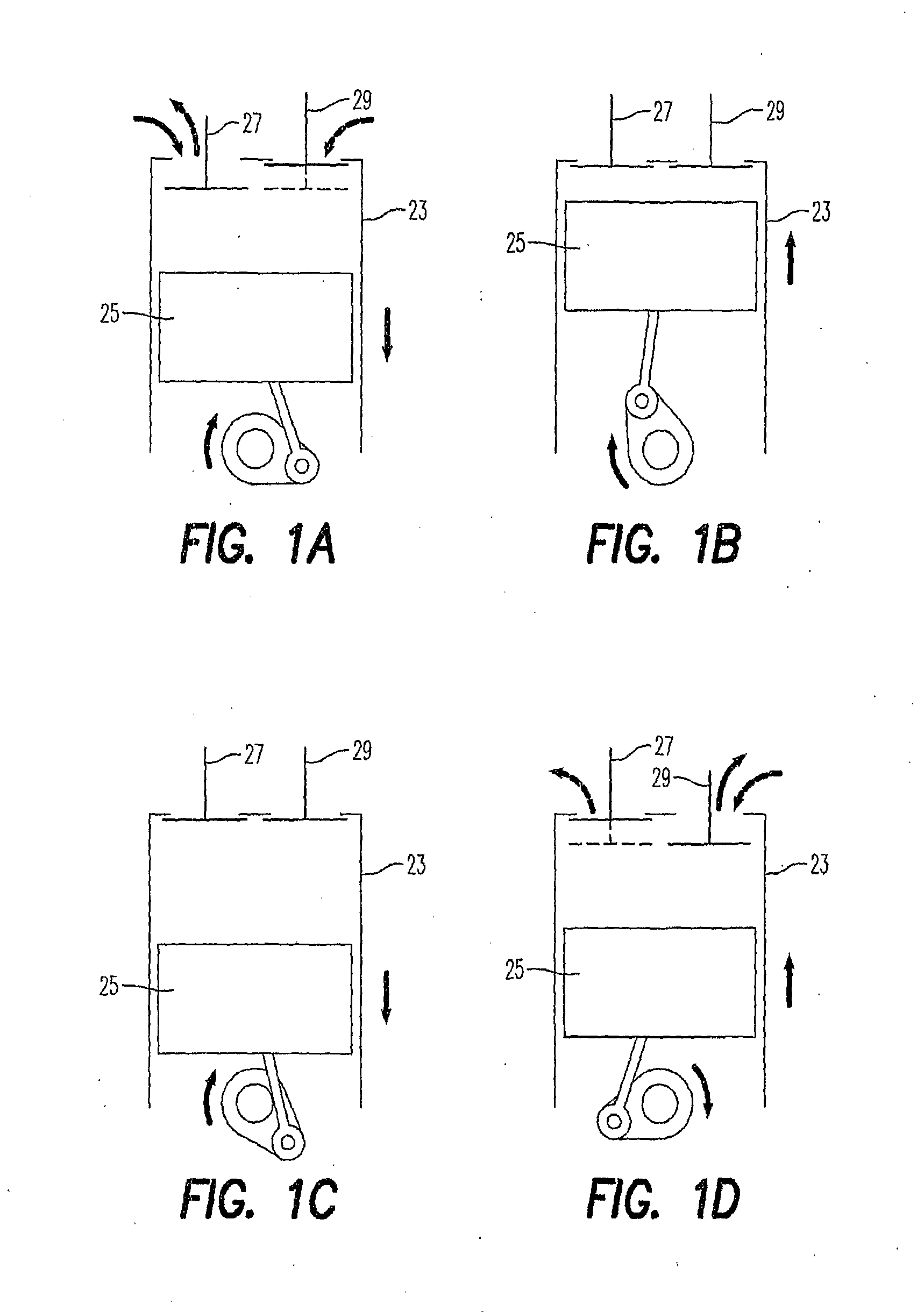
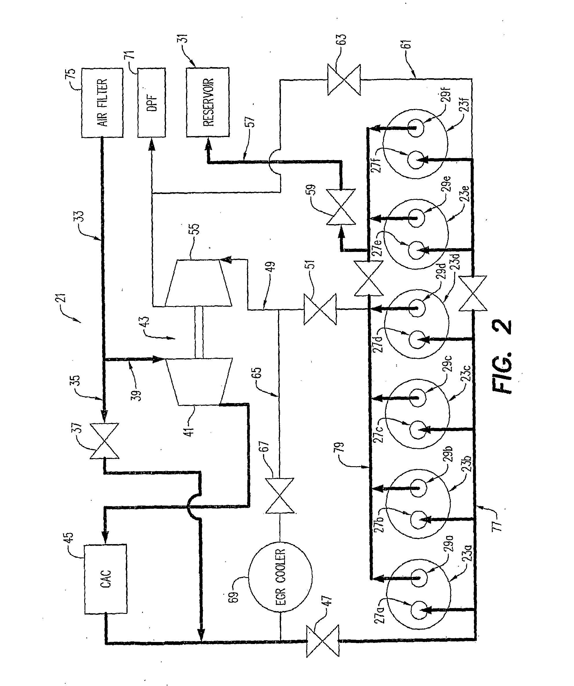
[0051]A hybrid internal combustion engine and air motor system 21 (generally referred to as a “system”, “engine”, or “motor” herein) is shown in FIGS. 2-6. The system 21 can be used to drive a variety of machines and is presently considered to have particular applicability in machines such as motor vehicles. The system 21 typically includes at least one chamber that may be of the type as shown in FIGS. 1A-1D, such as a cylinder 23, having a piston, such as a piston 25, and at least one intake valve 27 and at least one exhaust valve 29. While the invention will be described primarily in connection with a system 21 comprising a cylinder in the form of the cylinder 25 and a piston in the form of the piston 25, it will be appreciated that the invention is adapted to be used with other types of chamber / piston arrangements, such as rotary engines (not shown). It will also be appreciated that the invention can comprise a system having a plurality of chambers or cylinders. Typically, the cy...


PUM


Abstract

A hybrid internal combustion engine and air motor system is provided and includes at least one chamber having a drivable member and at least one intake valve and at least one exhaust valve, and a reservoir connected to the chamber through at least one of the intake valve and the exhaust valve. The system further comprises a computer configured to calculate air compressor efficiency during an air compressor mode of operation and select an intake and exhaust valve opening and closing timing sequence for maximizing air compressor efficiency and / or a computer configured to calculate air motor efficiency during an air motor mode of operation and select an intake and exhaust valve opening and closing timing sequence for maximizing air motor efficiency.

Description

BACKGROUND AND SUMMARY[0001]The present invention relates generally to hybrid internal combustion engine and air motor systems and methods and, more particularly, to such systems and methods wherein intake and exhaust valve opening and closing timing sequences during air motor or air compressor modes of operation are selected to maximize air motor efficiency or air compressor efficiency.[0002]Typical city driving patterns for vehicles include many accelerations and decelerations. A significant portion of fuel energy is spent in accelerating the vehicle. This energy is wasted during subsequent decelerations. A pneumatic hybrid engine captures and reuses some of this energy. During braking, the engine can utilize the braking energy to work as a compressor, pumping compressed air into an on-board tank. Later, during acceleration, the engine can be powered by the stored compressed air with or without burning diesel fuel to get up to speed or until the compressed air is depleted. The add...

Claims


Application Information

Patent Timeline
Patent Type & Authority Applications(United States)
IPC IPC(8): F04B49/00
CPCB60K6/12B60Y2400/435B60L2240/443B60T1/10B60W10/06B60W20/00B60W30/192B60W2510/0638B60W2510/0657B60W2550/12F02B21/00F02B29/00F02B29/0418F02D13/04F02D41/0007F02D41/0087F02D2041/001F02M25/0707F02M25/0727Y02T10/146Y02T10/6208B60W20/40F01L1/34B60L2240/441B60W2555/20F02M26/05F02M26/23Y02T10/12Y02T10/62B60W10/04
Inventor TAI, CHUN
Owner VOLVO LASTVAGNAR AB
Learn More