Hearing aid dryer

a hearing aid and dryer technology, applied in the field of hearing aid dryers, can solve problems such as device failure and damage, and achieve the effect of reducing humidity and reducing ultraviolet light emission

Active Publication Date: 2010-04-15
MG DEV AMERICA INC
View PDF8 Cites 28 Cited by
  • Summary
  • Abstract
  • Description
  • Claims
  • Application Information

AI Technical Summary

Benefits of technology

[0007]An electronic device drying and disinfecting apparatus includes an enclosure with an internal ultraviolet lamp for disinfecting the electronic device. A heating element creates an internal temperature to reduce humidity and a fan circulates air from the outside of th

Problems solved by technology

This exposes the devices to a warm, humid environment and presents the op

Method used


Image

  • Hearing aid dryer
  • Hearing aid dryer
  • Hearing aid dryer

Examples


Embodiment Construction

[0027]Reference will now be made in detail to the presently preferred embodiments of the invention, examples of which are illustrated in the accompanying drawings. Throughout the following detailed description, the same reference numerals refer to the same elements in all figures.

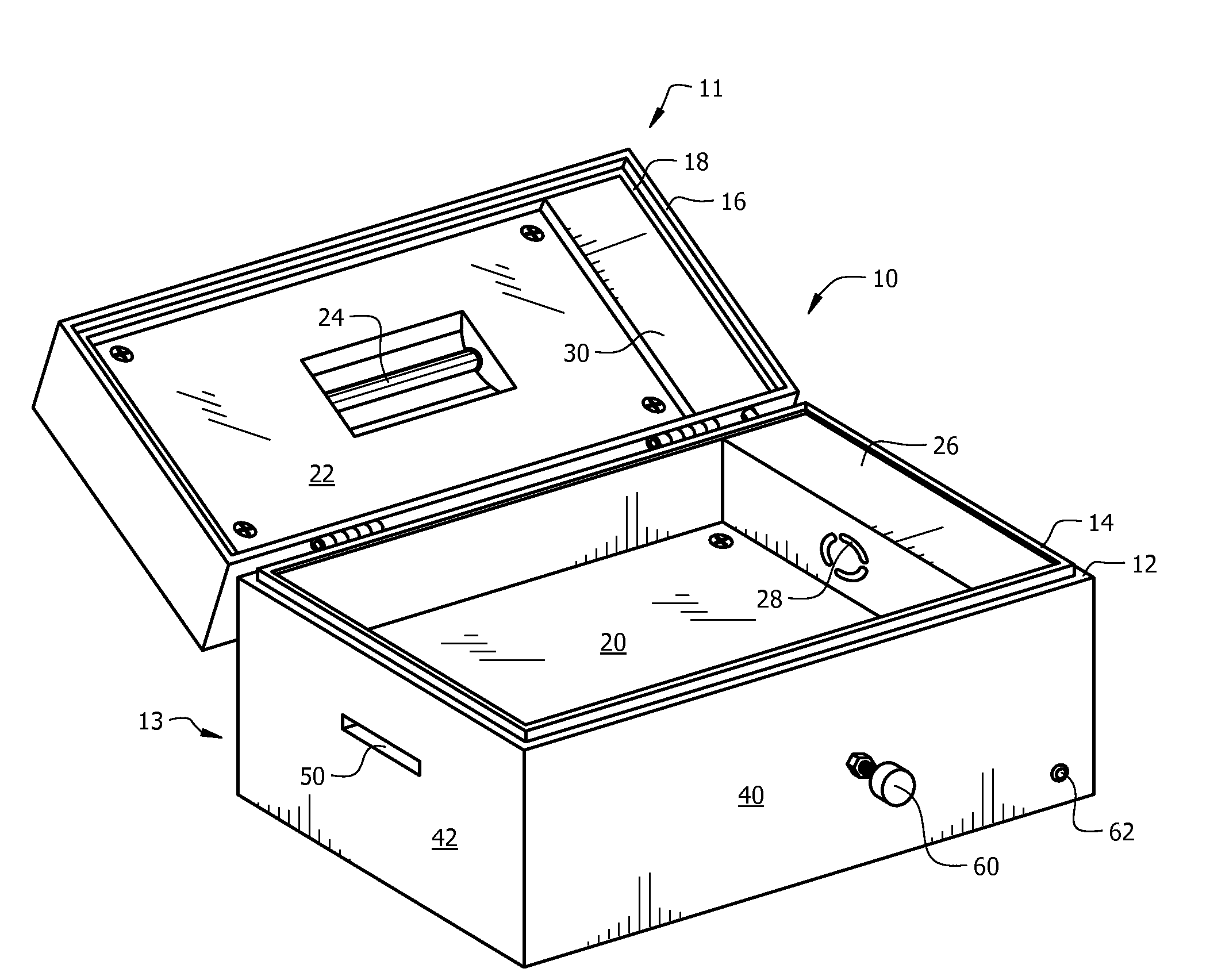
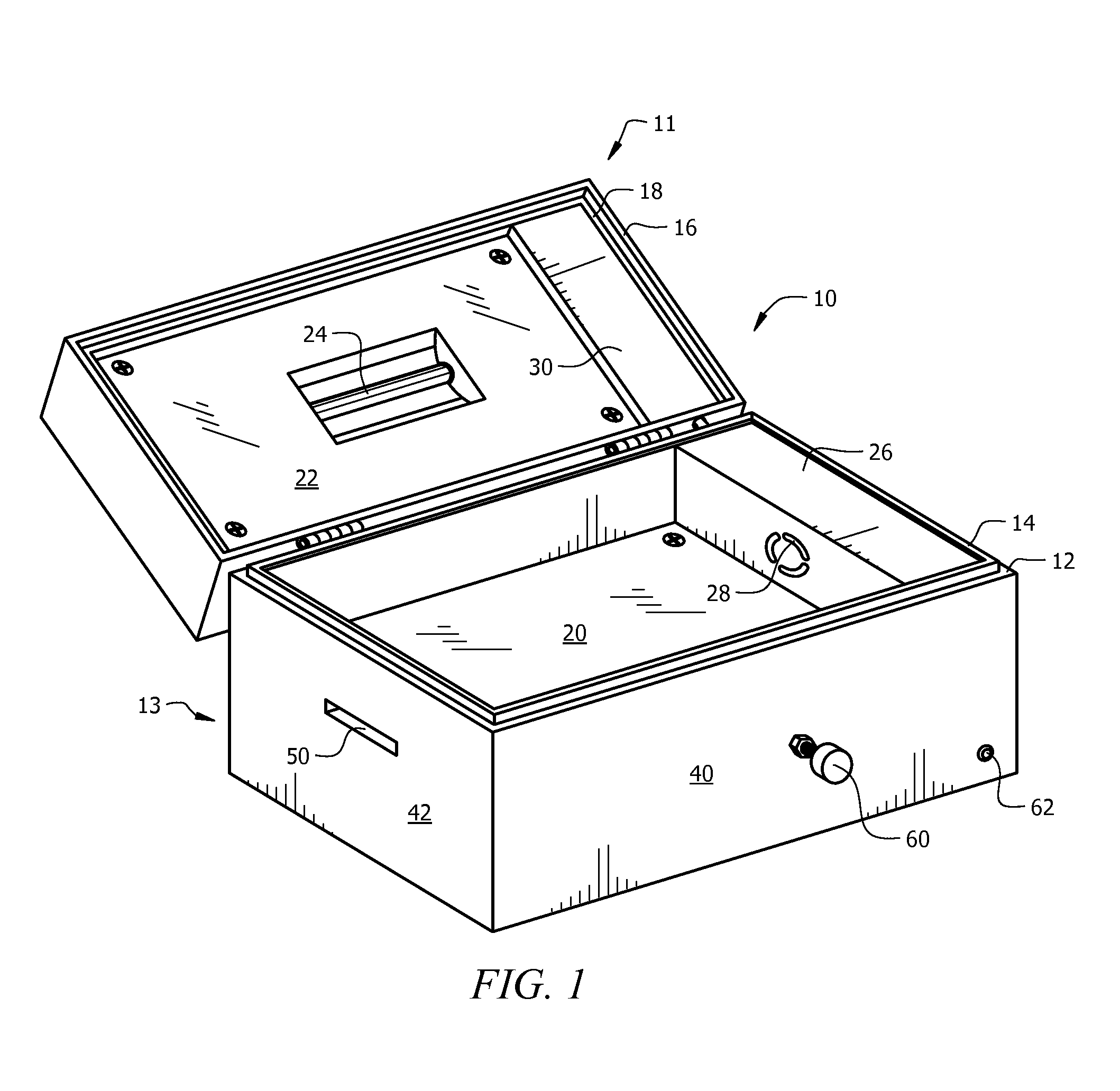
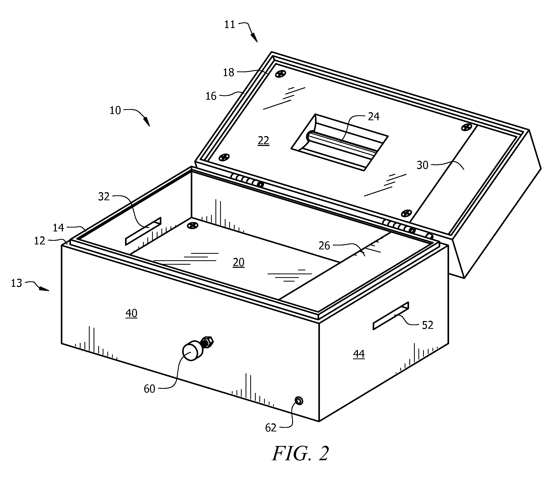
[0028]Referring to FIGS. 1 and 2, perspective views of an exemplary system 10 of the present invention with the lid open is shown. The hearing aid dryer 10 dries and disinfects a hearing aid 99 (see FIG. 6) or other electronic device using heat, a germicidal ultraviolet light and air flow without the use of a desiccant. Existing hearing aid dryers require a desiccant to remove humidity / moisture from within their sealed enclosure. The hearing aid dryer 10 performs its function without the use of a desiccant.

[0029]The hearing aid dryer 10 has a base portion 13 with a lid portion 11 hingedly attached to the base 13. The lid 11 contains an ultraviolet lamp 24 such as germicidal ultraviolet lamps as known in the...


PUM


Abstract

An application for a hearing aid drying/disinfecting system includes a closable container with an internally mounted ultraviolet lamp for disinfecting the hearing aid. A heating element creates an internal temperature that is higher than ambient temperature and a fan circulates air through vents from the outside of the container over the hearing aid and back out, thereby drying the hearing aid contained within the drying/disinfecting system. The vents are positioned to reduce ultraviolet emissions out of the container.

Description

RELATED APPLICATIONS[0001]This application is a continuation-in-part of co-pending application Ser. No. 12 / 249,578 filed Oct. 10, 2008.FIELD OF THE INVENTION[0002]This invention relates to an appliance for reducing moisture damage to sensitive electronic devices and more particularly to an appliance for reducing moisture in hearing aids.BACKGROUND[0003]Current trends in electronics have enabled the production of hearing aids small enough to reside partially or completely in the ear canal. This exposes the devices to a warm, humid environment and presents the opportunity for damage to the device and ultimately, failure of the device.[0004]There are several ways for hearing aid wearers to protect their devices from moisture damage while they are not being worn. The simplest device is a container having desiccant material inside and way to separate the device from the desiccant.[0005]U.S. Pat. No. 5,640,783 to Schumaier, U.S. Pat. No. 5,852,879 to Schumaier and U.S. Pat. No. 7,017,276 ...

Claims


Application Information

Patent Timeline
IPC IPC(8): F26B3/34
CPCF26B9/003F26B3/283
Inventor ROMANEK, HARVEY
Owner MG DEV AMERICA INC
Why Eureka
Try Eureka