Cutting machine particulary for leather and similar materials

a cutting machine and leather technology, applied in the direction of engine seals, leather clicking/perforating/clicking, leather/skin/hides/pelt mechanical treatment, etc., can solve the problems of time expenditure, inability to calculate, and the drawback of the known cutting machine described above, so as to achieve the effect of improving productivity

Active Publication Date: 2010-04-15
COMELZ SPA
View PDF8 Cites 9 Cited by
  • Summary
  • Abstract
  • Description
  • Claims
  • Application Information

AI Technical Summary

Benefits of technology

[0008]The aim of the present invention is to provide a cutting machine, particularly for leather and similar materials, which allows to perform in parallel the operations for detecting / processing the cutting data and the cutting operations, to the advantage of productivity.

Problems solved by technology

In view of the limited rigidity of the printed material, it is not possible to calculate in advance the exact position of the parts to be cut, but it is necessary to readjust a theoretical position calculated beforehand according to the actual position of the references of the material arranged in the cutting area.
However, the known types of cutting machines described above suffer the drawback of having to perform the three operations cited above before being able to proceed with the cutting of the material.
This of course entails an expenditure of time.
Moreover, with known types of systems it is not possible to perform in parallel the detection and processing operations and the cutting operations.

Method used


Image

  • Cutting machine particulary for leather and similar materials
  • Cutting machine particulary for leather and similar materials
  • Cutting machine particulary for leather and similar materials

Examples


Embodiment Construction

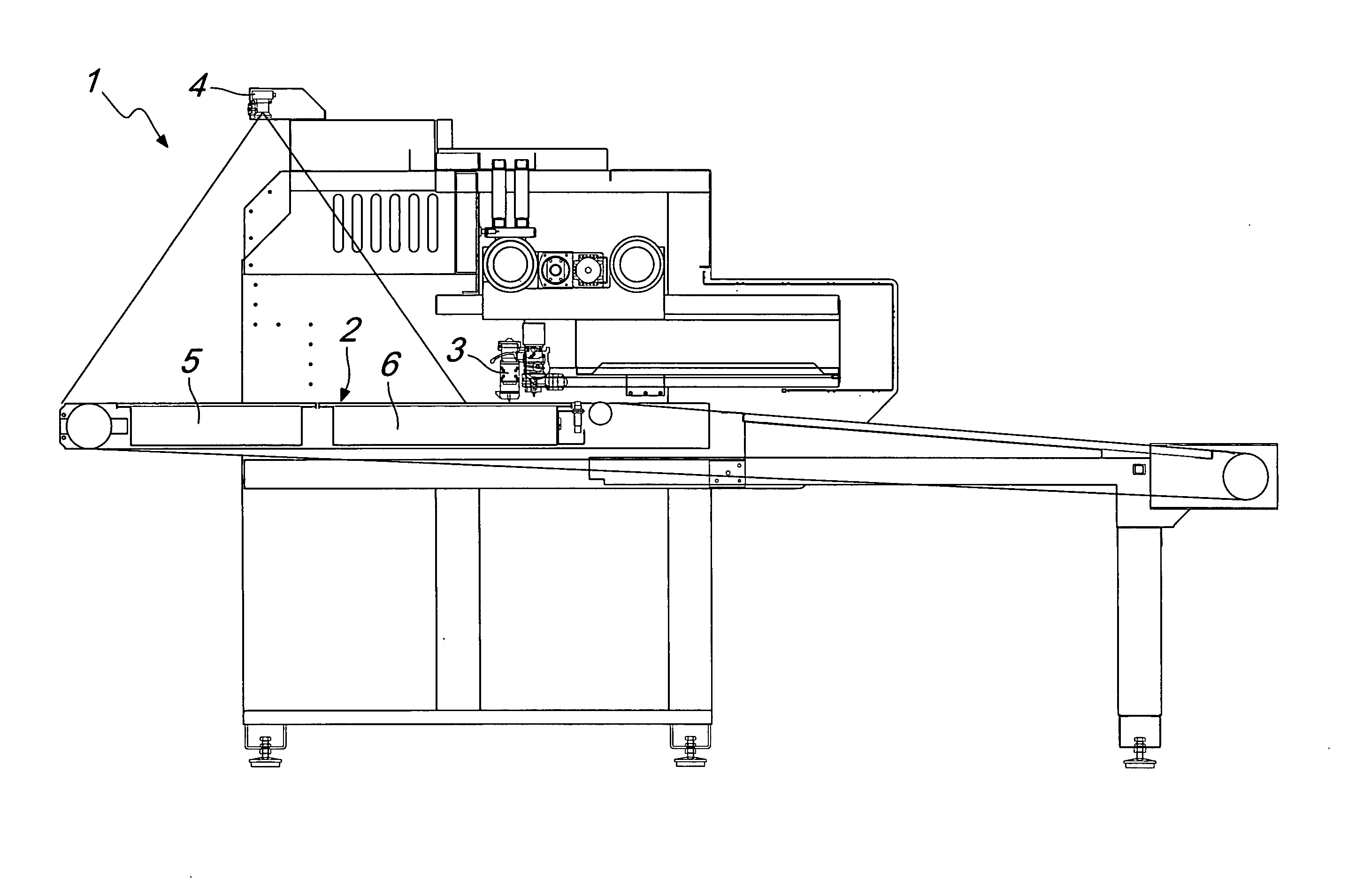
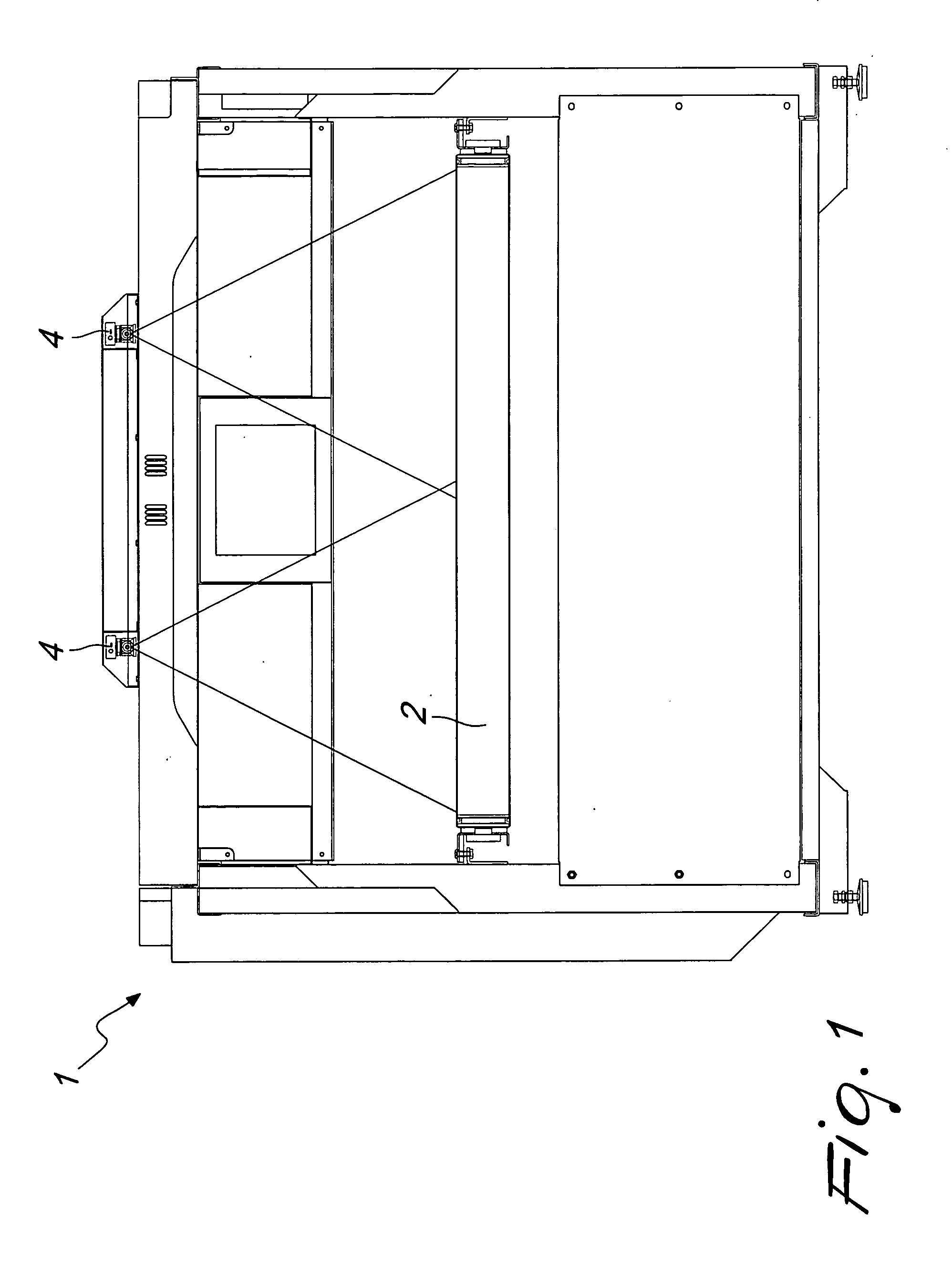
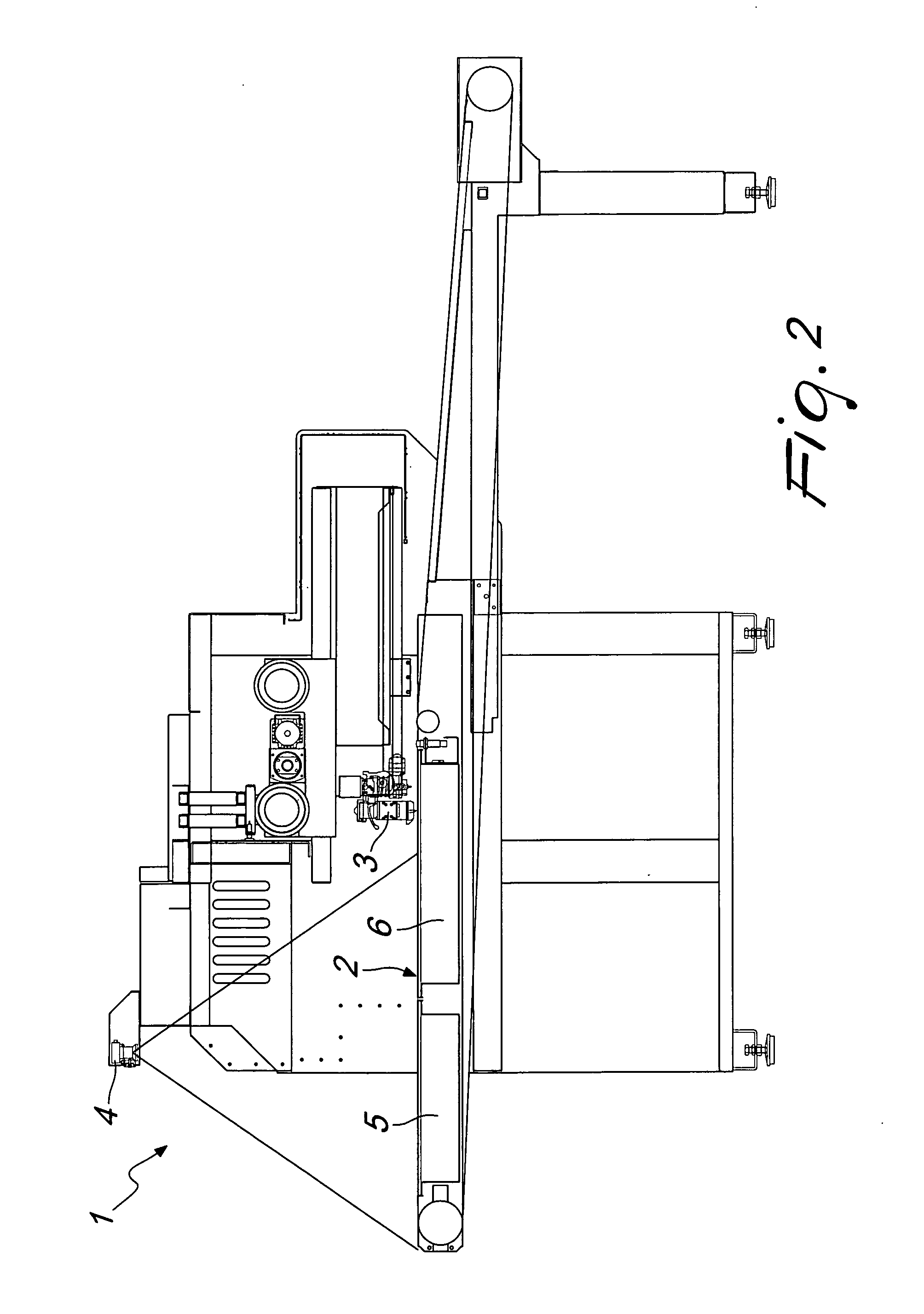
[0016]With reference to the figures, the cutting machine according to the present invention, generally designated by the reference numeral 1, comprises a conveyor belt 2, on which the material to be cut is arranged, and one or more cutting heads 3 arranged above the conveyor belt, the belt moving along the longitudinal extension of the machine.

[0017]One or more material detection means, such as TV cameras 4 are provided in order to detect the position of the material on the belt; the position of the parts is not detected but is entered by the machine taking into account the position of the references, thus detecting the exact layout of the references provided on the material.

[0018]Conveniently, the TV cameras 4 are provided at a detection area 5 which is arranged upstream of a cutting area 6. In the detection area 5, the one or more TV cameras 4 detect the exact layout with references provided on the material, so as to be able to perform in parallel the detection / processing operatio...


PUM

PropertyMeasurementUnit
areaaaaaaaaaaa
rigidityaaaaaaaaaa
timeaaaaaaaaaa

Abstract

A cutting machine, particularly for leather and similar materials, comprising a cutting area provided with one or more cutting heads and with an area for unloading the cut parts, the areas being arranged along a conveyor belt, material detection means being provided in order to detect the position of the material before cutting it, the machine further comprising a detection area, arranged upstream of the cutting area, the material detection means being arranged in the detection area in order to detect the position of references provided on the material to be cut.

Description

BACKGROUND OF THE INVENTION[0001]As is known, in cutting machines for leather and similar materials, which have a cutting area with one or more cutting heads and an area for unloading cut parts, arranged along a conveyor belt, it is often desirable to cut parts in an aligned manner, with a precision on the order of tenths of a millimeter on materials printed with references and logos.[0002]In view of the limited rigidity of the printed material, it is not possible to calculate in advance the exact position of the parts to be cut, but it is necessary to readjust a theoretical position calculated beforehand according to the actual position of the references of the material arranged in the cutting area.[0003]For this purpose, TV cameras are used which detect the exact position of the references printed on the material to be cut, in order to readjust the position of the parts before cutting them. This operation is normally performed when the material is already positioned in the cutting...

Claims


Application Information

Patent Timeline
Patent Type & Authority Applications(United States)
IPC IPC(8): C14B5/00
CPCB26D5/005C14B5/00B26F1/3813B26D5/007
Inventor ZORZOLO, STEFANO
Owner COMELZ SPA
Why Eureka
Try Eureka