Cutting machine, particularly for leather and similar materials

Active Publication Date: 2010-02-25
COMELZ SPA
View PDF3 Cites 14 Cited by
  • Summary
  • Abstract
  • Description
  • Claims
  • Application Information

AI Technical Summary

Benefits of technology

[0011]The aim of the present invention is to provide a cutting machine for leather and similar materials which provides a

Problems solved by technology

However, currently there are limitations as to the depth of the layout and to the cutting areas.
However, the force of the cutting head on the plane during cutting imparts a vertical force to the guides along the direction Y, which generates a flexing thereof which increases as the cantilever with which the heads work increases, consequently degrading the quality and continuity of the cutting action.
For this reason, the depth of the cantilever, and accordingly of the cutting area, has been contained within a level at which such flexing is acceptable, setting however limitations to the maximum depth of the parts that can be cut in a single pass (without pickups, which can cause problems in realignment precision) and forcing freque

Method used


Image

  • Cutting machine, particularly for leather and similar materials
  • Cutting machine, particularly for leather and similar materials

Examples


Embodiment Construction

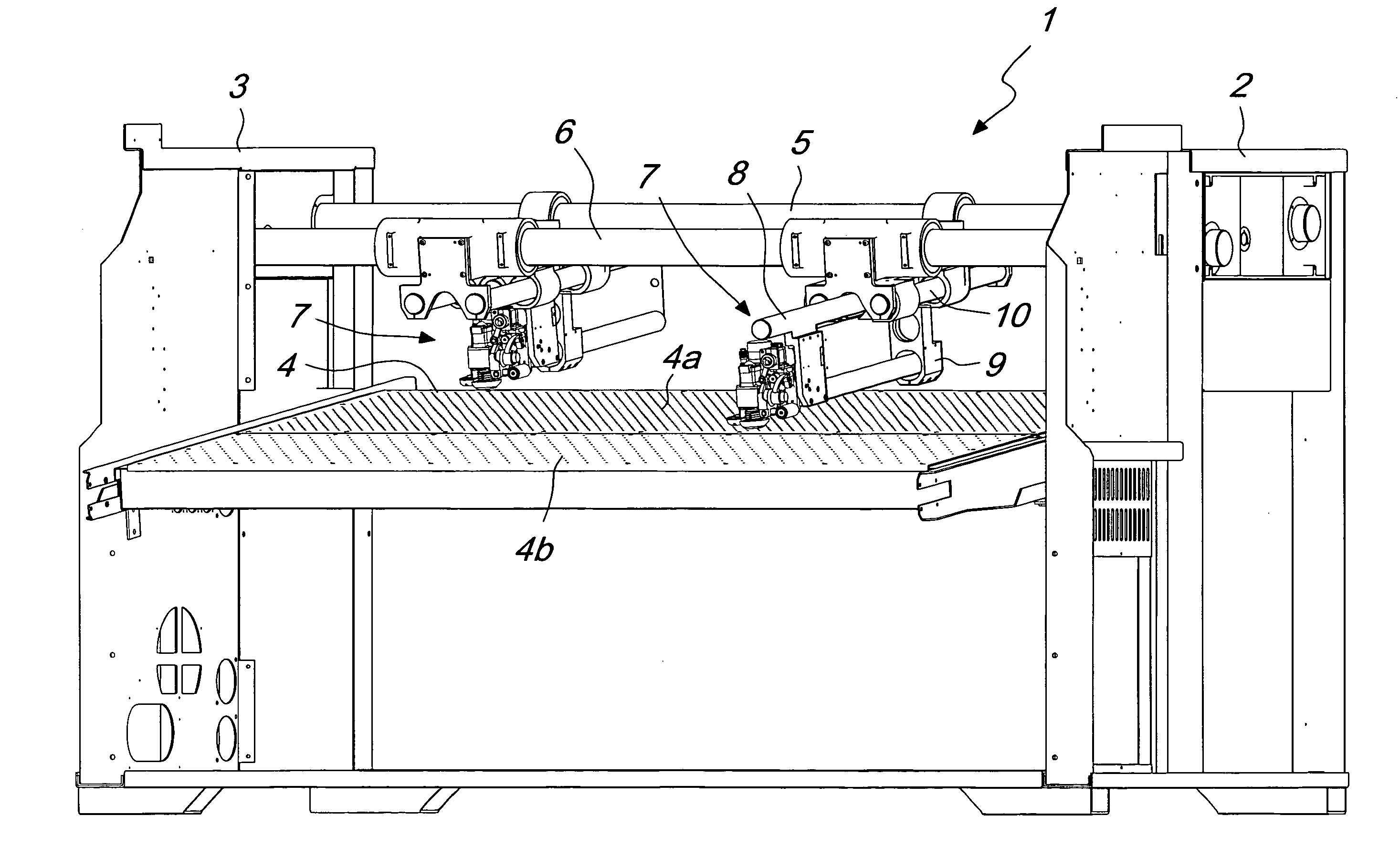
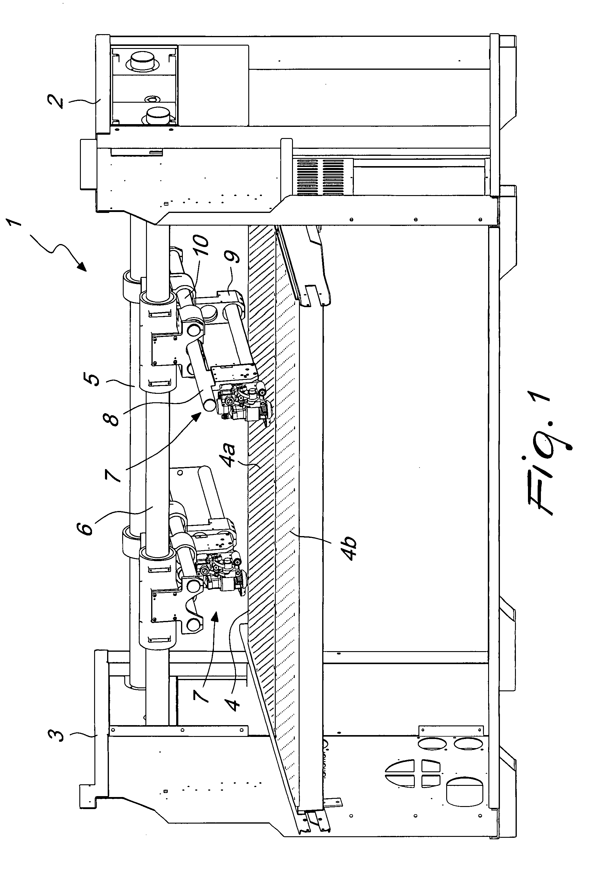
[0018]With reference to the figure, the cutting machine according to the present invention, generally designated by the reference numeral 1, comprises a machine frame constituted by a pair of shoulders 2 and 3, which are arranged so as to face each other and between which there is a conveyor belt (not shown in the figure) which can move transversely with respect to a pair of guides 5 and 6 which lie above the conveyor belt and are connected to the shoulders 2 and 3.

[0019]The conveyor belt surmounts a worktable 4 of the machine, which is divided into a cutting area 4a and a layout area 4b.

[0020]The cutting area 4a and the layout area 4b are connected to a suction tray, which is activated during work so as to create a suitable partial vacuum which is sufficient to keep the leather to be cut in position. The suction acts through holes, shown schematically in FIG. 1, whose distribution is denser in the cutting area 4a, so as to create a higher partial vacuum, and less dense in the layo...


PUM


Abstract

A cutting machine, particularly for leather and similar materials, comprising a pair of shoulders which are connected by a system of guides arranged so as to lie above a conveyor belt, at least one cutting head being movable along the guide system, the movement of the cutting head in the same advancement direction as the conveyor belt and at right angles to the guide system being distributed on two or more elements, at least one of which is cantilevered.

Description

[0001]The present invention relates to a cutting machine, particularly for leather and similar materials. More particularly, the invention relates to a cutting machine provided with at least one cutting head which can move along two mutually perpendicular axes.BACKGROUND OF THE INVENTION[0002]As is known, cutting machines for leather and similar materials have a layout area, on which contours are arranged by projection, a cutting area, with one or more cutting heads, and finally an area for unloading the cut parts.[0003]The mentioned areas lie along a conveyor belt on which the parts to be cut are arranged.[0004]However, currently there are limitations as to the depth of the layout and to the cutting areas.[0005]In known solutions, the cutting area is covered by two cutting heads, each of which is mounted so as to be jointly connected to the end of a system of guides which slides, in a cantilever arrangement along a longitudinal direction Y, i.e., transversely to the advancement dir...

Claims


Application Information

Patent Timeline
IPC IPC(8): C14B5/00
CPCB23Q1/621C14B5/00B26F1/3813B26D7/018
Inventor ZORZOLO, ALESSANDROZORZOLO, STEFANO
Owner COMELZ SPA
Why Eureka
Try Eureka