Synthetic resin bottle

a technology of synthetic resin and bottle, applied in the field of synthetic resin bottles, can solve the problems of large design problems of bottle bottles, difficult to secure satisfactorily both the vacuum-absorbing function of vacuum-absorbing panels and the rigidity of bottles, and achieve the effects of reducing design restrictions, reducing the risk of bottle deformation, and improving rigidity and strength in the lateral direction

Active Publication Date: 2010-04-15
YOSHINO KOGYOSHO CO LTD
View PDF4 Cites 21 Cited by
  • Summary
  • Abstract
  • Description
  • Claims
  • Application Information

AI Technical Summary

Benefits of technology

[0037]In the invention of claim 6, the connection of the pillar sections with the upper and lower circular sections is strengthened by extending the width of the upper base and the lower base of each pillar section. As a result, load is dispersed more effectively, and the rigidity and strength in the lateral direction can be

Problems solved by technology

With a trend toward thin body wall intended for material cost reduction, the bottle shape design has to face large problems, including how to secure full strength and rigidity as the bottle and how to obscure the body wall deformation caused by pressure fluctuation inside the bottle.
This bottle is used for the so-called hot filling process in which the bottle is filled with such contents as juice, tea, etc., which require sterilization at about 90 degrees C. Since the bottle is filled with the contents at about 90 degrees C., then capped, sealed, and cooled, the bottle inside is put under a fairly reduced pressure condition, and the bottle wall deformation becomes problematic.
However, small bottles with a capacity of 350 ml or 280 ml have a problem in that they are limited in the area where vacuum-absorbing panels can be formed, as compared to larger bottles, thus making it difficult to secure satisfactorily both of the vacuum-absorbing function of the vacuum-absorbing panels and the rigidity of the bottle.
The bottle rigidity in the vertical direction can be secured relatively easily by the upright pillar sections 115 shown in FIG. 5, but the

Method used


Image

  • Synthetic resin bottle
  • Synthetic resin bottle
  • Synthetic resin bottle

Examples


Embodiment Construction

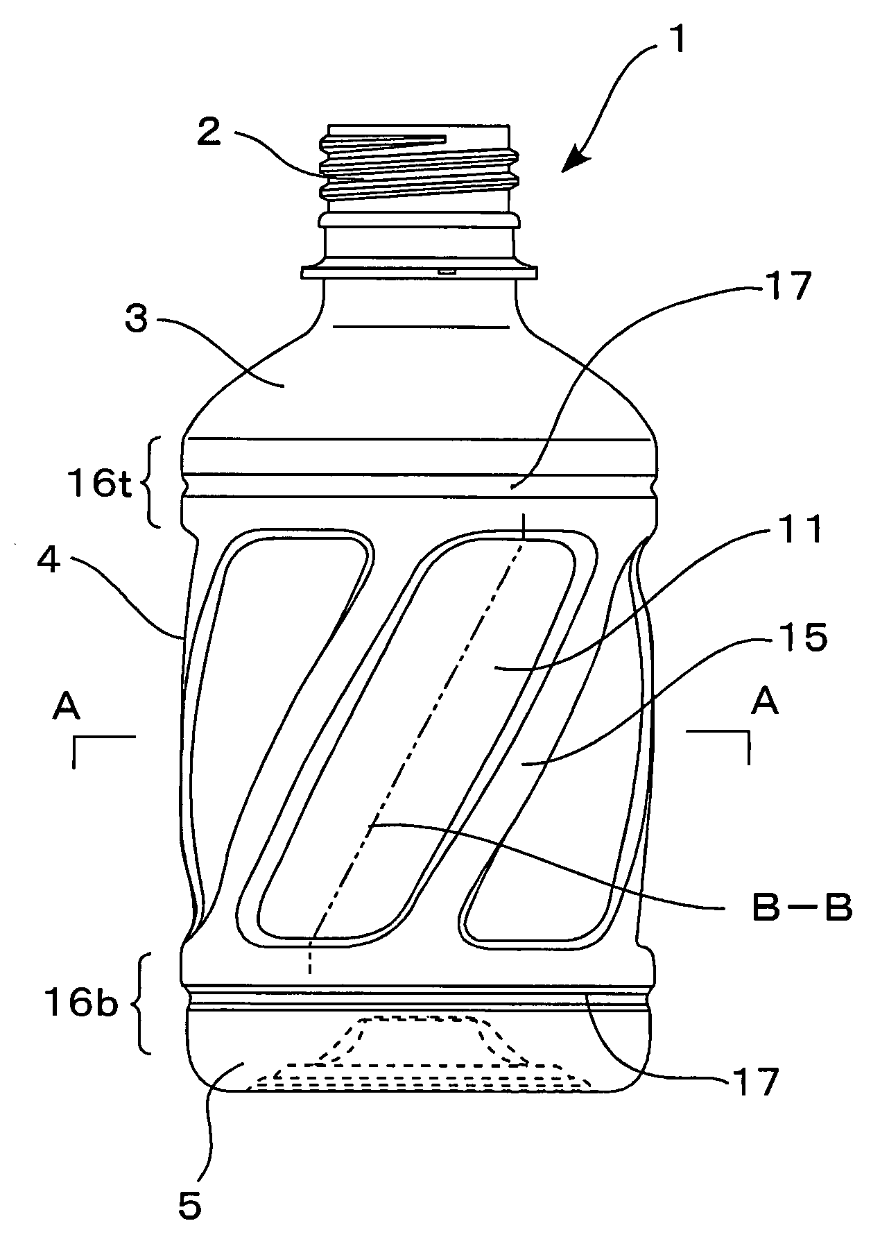
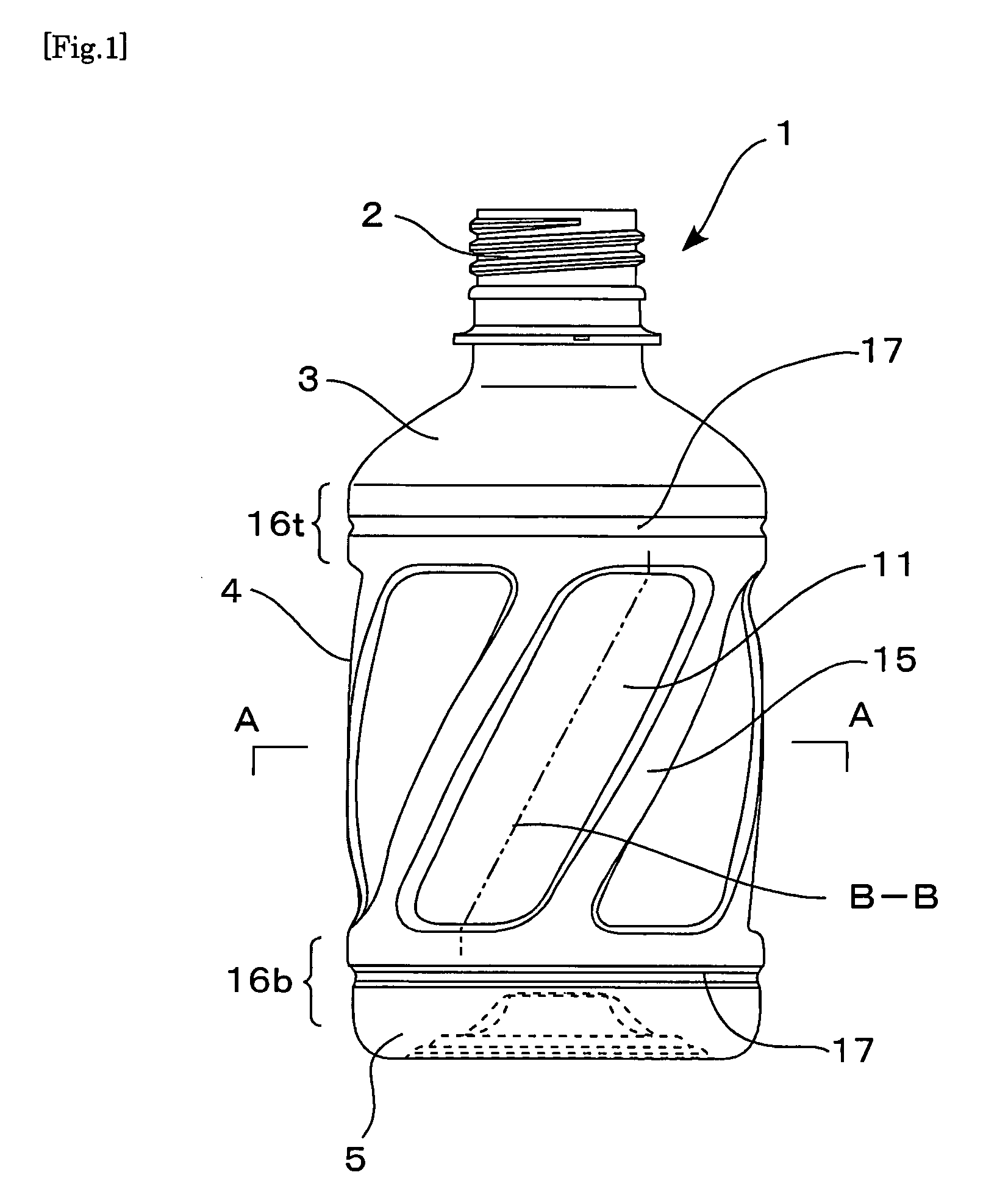
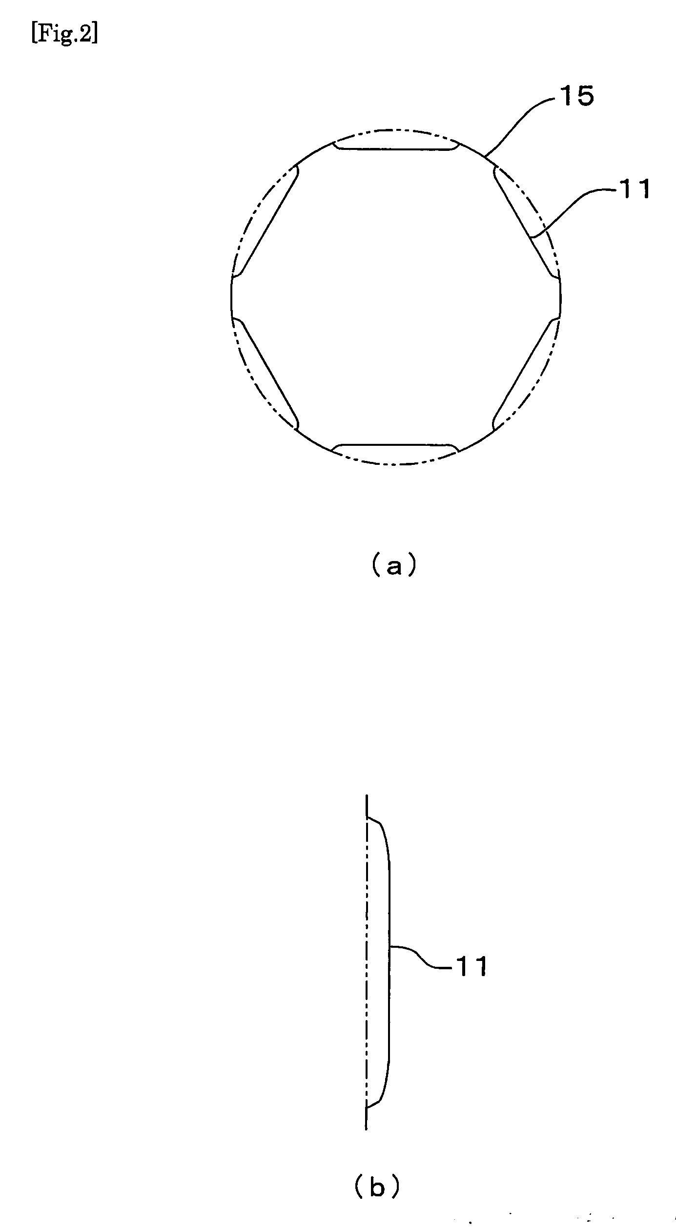
[0072]This invention is further described with respect to preferred embodiments, now referring to the drawings. FIGS. 1-3 show the synthetic resin bottle in one embodiment of this invention. FIG. 1 is a front elevational view of the bottle. FIG. 2(a) is a cross-sectional view of the bottle taken from line A-A in FIG. 1, and FIG. 2(b) is a vertical section of a later-described vacuum-absorbing panel 11 taken along line B-B, showing its dented shape. The bottle 1 is s biaxially drawn, blow molded product made of a PET resin. It is a small round bottle comprising a neck 2, a shoulder 3, a body 4, and a bottom 5, and the body 4 has a nominal capacity of 280 ml. The bottle has a total height of 132 mm, a maximum diameter Do of 66 mm, and a weight of 19 g.

[0073]Six vacuum-absorbing panels 11 are an embodiment of dented panels, and are formed by denting portions of cylindrical wall of the body 4 in a certain height range of the body 4. These panels are roughly flat plates and are in the sh...


PUM


Abstract

The technical problem to be solved by this invention is to design a bottle shape that improves the bottle rigidity and strength in the lateral direction, without increasing the cost of material required to thicken the bottle wall. The object of this invention is to provide a synthetic resin bottle at a low cost in such a way that the bottles can be used smoothly on the carrier line, in the vending machines, and in storage on the stacks with no deformation, and are capable of performing a vacuum-absorbing function enough to be used in hot filling. Multiple pillar sections in a projected strip-like shape are disposed on the body of a synthetic resin bottle, wherein the pillar sections are inclined spirally at a uniform angle of gradient (α) relative to central axis of the bottle and disposed in parallel to one another, so that the cylindrical body wall is prevented from being deformed by the pressure force that acts in a lateral direction.

Description

TECHNICAL FIELD[0001]This invention relates to a synthetic resin bottle, and in particular, to a synthetic resin bottle that resists deformation caused by pressure force coming from a lateral direction.[0002]Synthetic resin bottles made of a polyethylene terephthalate resin (hereinafter referred to as a PET resin) and the like have been in wide use until today as the containers for various drinks. With a trend toward thin body wall intended for material cost reduction, the bottle shape design has to face large problems, including how to secure full strength and rigidity as the bottle and how to obscure the body wall deformation caused by pressure fluctuation inside the bottle.[0003]For example, patent document 1 includes descriptions concerning a bottle having vacuum-absorbing panels in the body portion. This bottle is used for the so-called hot filling process in which the bottle is filled with such contents as juice, tea, etc., which require sterilization at about 90 degrees C. Si...

Claims


Application Information

Patent Timeline
IPC IPC(8): B65D90/02
CPCB65D1/42B65D1/0223B65D1/02
Inventor OGUCHI, HIROKIOZAWA, TOMOYUKIIIZUKA, TAKAO
Owner YOSHINO KOGYOSHO CO LTD
Why Eureka
Try Eureka