Dimmable lighting system

Active Publication Date: 2010-04-15
SIGNIFY HLDG BV +1
View PDF14 Cites 96 Cited by
  • Summary
  • Abstract
  • Description
  • Claims
  • Application Information

AI Technical Summary

Benefits of technology

[0019]In yet another aspect, the invention relates to a lighting system for operation with a dimmer circuit comprising a triac, where the system comprises a light source comprising one or more LEDs and a load comprising a dimmer triggering circuit for triggering the dimmer triac and a driver circuit for supplying a current to the one or more LEDs, wherein the current supplied by the driver circuit is determined at least in part by an dimmer setpoint value, and wherein the dimmer setpoint value is derived at least in part from a firing angle of the dimmer triac.
[0020]The driver circuit preferably derives the dimmer setpoint value from a time delay between a zero crossing of a supply voltage and a first triggering of the triac after the zero crossing point. The dimmer setpoint value may be determined at least in part by a time of occurrence of one or more rising and/or falling edges of a current flowing though a dimmer triggering circuit, or a voltage related to the rising edge and falling edge. The dimmer setpoint value may be determined at least in part by a time delay between a rising edge and a falling edge of a current flowing though a dimmer triggering circuit, or a voltage related to the rising edge and falling edge.
[0021]The driver circuit may comprise a voltage control circuit and a current control circuit, wherein the voltage control circuit controls the voltage at an output of the driver circuit according to a voltage setpoint, and the current control circuit modifies the voltage setpoint according to a current setpoint. T

Problems solved by technology

When these dimmers are used with smaller loads, such as light sources based on light-emitting diodes (LEDs), various problems are encountered.
This is a particular problem when replacing standard incandescent light bulbs with LED retrofit light bulbs in situations where a conventional triac dimmer has been installed for use with the light bulb.
An LED light source may not draw enough current to permit the triac in

Method used


Image

  • Dimmable lighting system
  • Dimmable lighting system
  • Dimmable lighting system

Examples


Embodiment Construction

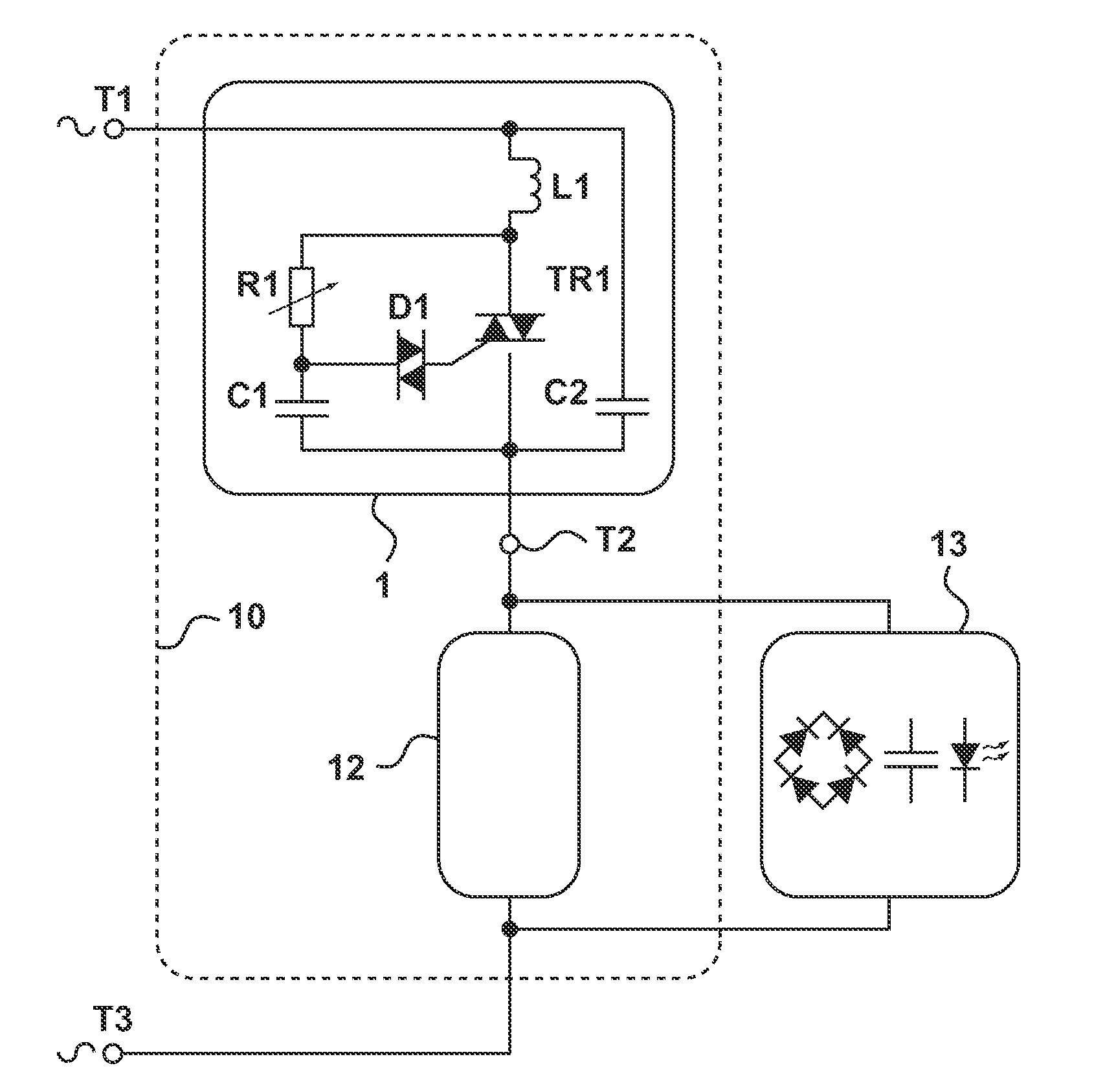
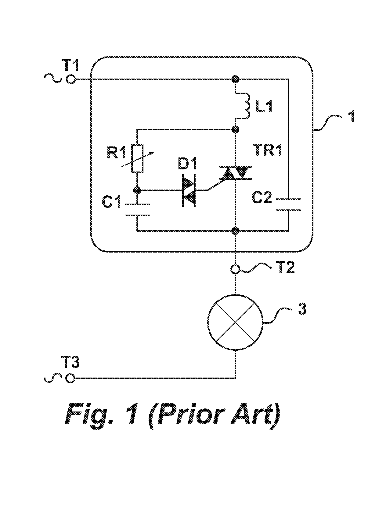
[0038]The following is a description of certain embodiments of the invention, given by way of example only. FIG. 1 schematically shows a conventional dimmer 1 connected to a load 3, typically an incandescent light bulb. The dimmer 1 comprises a triac TR1 connected in parallel with a variable resistor R1 and a capacitor C1 in series. In this description, the combination of resistor R1 and capacitor C1 will be referred to as an RC circuit or timer circuit. Additionally, the dimmer comprises a triggering component, i.e. a component suitable to trigger the triac TR1. Generally, a Diode for Alternating Current (diac) is used for this purpose. A diac is a bidirectional trigger-diode that conducts current after a diac threshold voltage, also referred to as the diac trigger voltage, has been exceeded. A diac remains conducting while the current flowing through it remains above a threshold current. If the current decreases below the threshold current, the diac switches back to a high-resista...


PUM


Abstract

A lighting system for operation with a dimmer circuit comprising a triac connected to a load. The load comprises a driver circuit for supplying current to a light source comprising one or more LEDs, the current being determined at least in part by an adjusted setpoint value. The system further comprises a setpoint filter circuit for obtaining a dimmer setpoint value determined at least in part by a setting of the dimmer circuit, and for generating an adjusted setpoint value. The sensitivity of the adjusted setpoint value to changes in the dimmer setpoint value is low at low values of the dimmer setpoint value.

Description

[0001]This application is a continuation-in-part of U.S. application Ser. No. 12 / 146,512 filed on Jun. 26, 2008, which claims priority from provisional application No. 61 / 042,289 filed on Apr. 4, 2008. The contents of both applications are hereby incorporated by reference in their entirety.BACKGROUND OF THE INVENTION[0002]1. Field of the Invention[0003]The present invention relates to a dimmer triggering circuit for low-load applications, e.g. LED-based light sources. The invention further relates to a dimmer system comprising such a dimmer triggering circuit.[0004]2. Description of the Related Art[0005]Generally, phase-controlled dimmers comprise a triode for alternating current, further referred to as a triac. A triac is a bidirectional switch which can conduct current in either direction when it is triggered, i.e. turned on. It can be triggered by either a positive or a negative voltage being applied to its gate electrode, i.e. when a small current is applied to its gate. This cu...

Claims


Application Information

Patent Timeline
IPC IPC(8): H05B37/02
CPCH05B33/0815Y02B20/383H05B33/0839H05B33/0821H05B45/40Y02B20/30H05B45/385H05B45/38
Inventor VELTMAN, ANDRE
Owner SIGNIFY HLDG BV
Why Eureka
Try Eureka