Feed device

Inactive Publication Date: 2010-04-15
NEC CORP
8 Cites 5 Cited by

AI-Extracted Technical Summary

Problems solved by technology

The terminals for use in the foregoing services have been miniaturiz...

Benefits of technology

[0015]According to the present invention, the conductors are connected to the radiating elements in terms of alternating current through capacitive coupling. This provides the effect...

Abstract

There is provided a less fragile feeding apparatus for an antenna that can be fitted to clothing. The feeding apparatus uses a coaxial cable for feeding. A center conductor of the coaxial cable is connected to a first radiating element in terms of alternating current at least through capacitive coupling, and an outer conductor of the coaxial cable is connected to a second radiating element in terms of alternating current at least through capacitive coupling.

Application Domain

Technology Topic

Image

  • Feed device
  • Feed device
  • Feed device

Examples

  • Experimental program(9)

Example

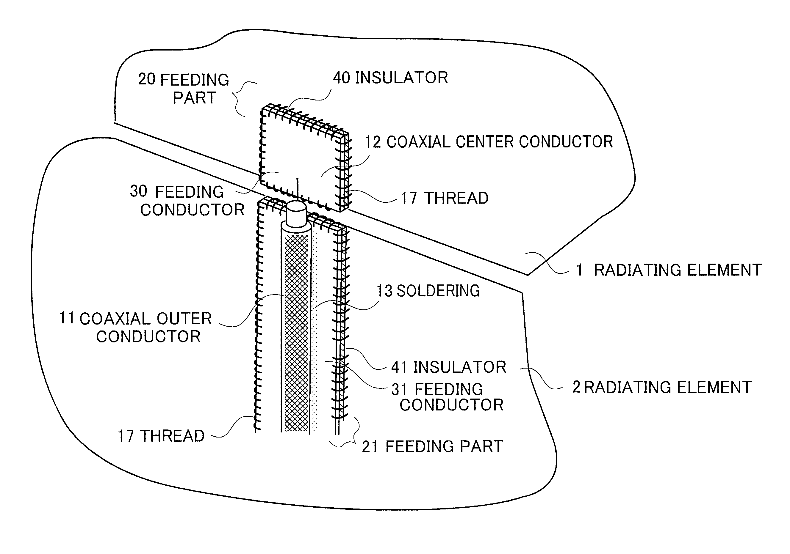
[0036]FIG. 1 is a configuration diagram of a first embodiment of the feeding apparatus according to the present invention. Radiating elements 1 and 2 of arbitrary shape are made of a flexible printed circuit board, conductive cloth, or the like that is flexible. A feeding part 20 includes a feeding conductor 30 and an insulator 40. Typically, the feeding part 20 is integrally made of a flexible printed circuit board or thin printed circuit board. A feeding part 21 similarly includes a feeding conductor 31 and an insulator 41. Like the feeding part 20, the feeding part 21 is integrally made of a flexible printed circuit board or thin printed circuit board. The feeding parts 20 and 21 are sewn on and fixed to the radiating elements 1 and 2 with a thread 17, respectively.
[0037]The thread 17 may be an ordinary non-conductive thread, a conductive thread, or a conductive wire.
[0038]A coaxial center conductor 12 is soldered to the feeding conductor 30, and a coaxial outer conductor 11 is soldered to the feeding conductor 31. There are generated capacitance between the feeding conductor 30 and the radiating elements 1 and capacitance between the feeding conductor 31 and the radiating element 2. The feeding conductors 30 and 31 provide the same effect as a direct connection does in terms of high frequencies if the insulators 40 and 41 are made of a sufficiently thin material to increase the capacitance between the feeding conductor 30 and the radiating element 1 and the capacitance between the feeding conductor 31 and the radiating element 2 so that the capacitance values make a sufficiently small reactance at the use frequency. The thicknesses of the insulators 40 and 41 and the areas of the feeding conductors 30 and 31 can be adjusted to modify the capacitances, thereby allowing adjustments for impedance matching when feeding the radiating elements 1 and 2.
[0039]Since the feeding parts 20 and 21 are made of a flexible printed circuit board and sewn with the thread 17, the feeding parts 20 and 21 have the advantage of high conformability to cloth, with no uncomfortable feeling or fragility even when mounted on clothing etc.

Example

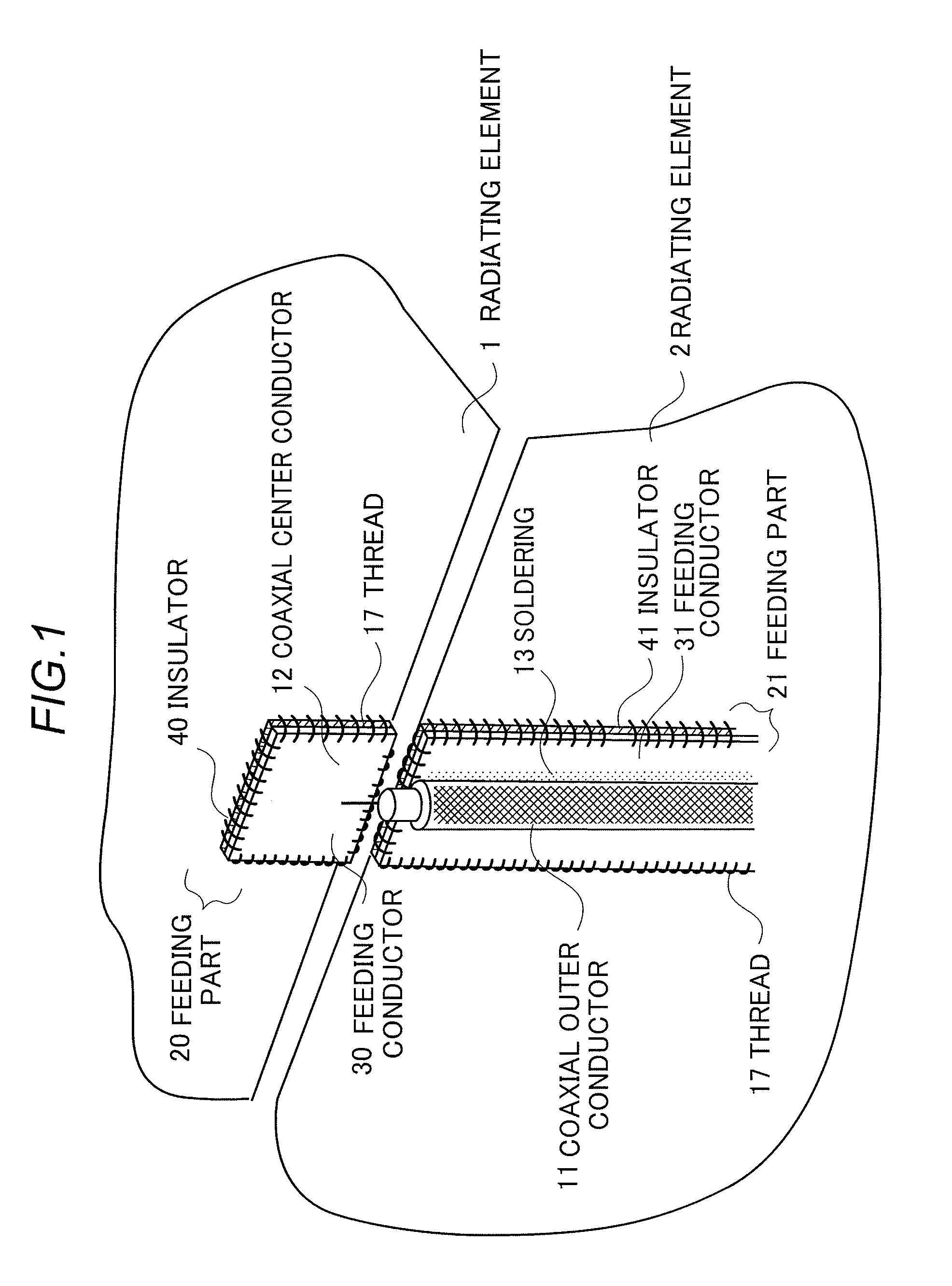
[0040]FIG. 2 is a configuration diagram of a second embodiment of the feeding apparatus according to the present invention. A base 50 is made of soft flexible material such as cloth. Radiating elements 51 and 52 of arbitrary shape are made of conductor cloth, a flexible printed circuit board, or the like that is flexible, and are sewn on the base 50 with a thread 53. A Velcro™54 is sewn on near the intended feeding positions of the radiating elements 51 and 52 with the thread 53. Note that the radiating elements 51 and 52, and the Velcro™54 may be bonded with an adhesive or with the adhesive of a heat transfer sheet instead of the thread 53. A feeding unit 60 is configured to be attached to the Velcro™54 for feeding.
[0041]FIG. 3 is a detailed view of the feeding unit 60. The feeding unit 60 includes a Velcro™61 and a printed circuit board 62. The Velcro™61 is intended to join the feeding unit 60 to the Velcro™54 on the radiating-element side in FIG. 2. The printed circuit board 62 is made of a flexible printed circuit board, thin printed circuit board, or the like that is flexible, and has feeding conductors 63 and 64 as a conductor pattern on its surface. A coaxial center conductor 12 of a coaxial cable 10 is soldered to the feeding conductor 63. A coaxial outer conductor 11 is soldered to the feeding conductor 64. When the feeding unit 60 is attached, there are generated capacitance between the feeding conductor 63 and the radiating element 51 and capacitance between feeding conductor 64 and the radiating element 52, so that feeding is performed by the principle described in FIG. 1.

Example

[0042]FIG. 4 is a configuration diagram of a third embodiment of the feeding apparatus according to the present invention. As in FIG. 2, a base 50 is made of soft flexible material such as cloth. Radiating elements 51 and 52 of arbitrary shape are sewn on the base 50 with a thread 53. A hook 70 is sewn on the intended feeding position of the radiating element 51 with a thread. A Velcro™71 is sewn on near the intended feeding position of the radiating element 52 with the thread 53. Again, the Velcro™71 may be fixed with an adhesive or the like instead of the thread 53 as mentioned previously.
[0043]A feeding unit 80 includes a hook 81 and a Velcro™82, which can be attached to the hook 70 and the Velcro™71, respectively, so that the feeding unit 80 is in close contact with the base 50 to feed the radiating elements 51 and 52.
[0044]FIG. 5 is a detailed view of the feeding unit 80. The feeding unit 80 has two possible configurations (1) and (2).
[0045]In the configuration (1), the feeding unit 80 includes a metal fitting 83 which is made of a conductor, a printed circuit board 86, and a Velcro™82. A hook 81 is integrally formed with the metal fitting 83. The metal fitting 83 is fixed so as to sandwich the top of the printed circuit board 86 which is made of a thin dielectric. Here, the metal fitting 83 may be effectively fixed with an adhesive, screws, grommets, and other means. The Velcro™82 is attached to the lower part of the printed circuit board. Again, the Velcro™ may be fixed with a thread 85, an adhesive, and various other means. The use of the thread 85 is effective if the printed circuit board 86 is an extremely thin member like a flexible printed board. A feeding conductor 88 is formed on the back side of the printed circuit board 86 as an etched conductor pattern. As in FIG. 3, a coaxial center conductor 12 and a coaxial outer conductor 11 of a coaxial cable 10 are soldered to the backside of the metal fitting 83 and the feeding conductor 88, respectively, so that the feeding unit 80 can perform feeding.
[0046]The configuration (2) differs from the configuration (1) in that the metal fitting 83 is divided into a metal fitting 89 and a feeding conductor 87. Here, the hook 81 is integrally formed with the metal fitting 89. The feeding conductor 87 is fixed to the metal fitting 89 with conductor screws 90 so that the printed circuit board 86 is sandwiched therebetween. Adhesives, grommets, staples, and other fixing means may be used instead of the screws 90. As in the description of the configuration (1), a coaxial center conductor 12 and a coaxial outer conductor 11 of a coaxial cable 10 are then soldered to the feeding conductor 87 and the feeding conductor 88, respectively, so that the feeding unit 80 can perform feeding.
[0047]According to the configurations of FIGS. 4 and 5, the radiating element 52 and the feeding conductor 88 are connected with each other in terms of high frequencies through their capacitance in the area where the Velcro™71 is joined to the Velcro™82. For the radiating element 51, the hooks 70 and 81 make an electrical contact with each other for feeding.

PUM

no PUM

Description & Claims & Application Information

We can also present the details of the Description, Claims and Application information to help users get a comprehensive understanding of the technical details of the patent, such as background art, summary of invention, brief description of drawings, description of embodiments, and other original content. On the other hand, users can also determine the specific scope of protection of the technology through the list of claims; as well as understand the changes in the life cycle of the technology with the presentation of the patent timeline. Login to view more.

Similar technology patents

Classification and recommendation of technical efficacy words

Why Eureka
Try Eureka