
Improving receiver performance in a communication network

a communication network and receiver technology, applied in the field of communication systems, can solve problems such as degrading performance, dvb waveforms may suffer inter-carrier interference, and channel estimates may not be perfect, and achieve the effect of improving the system error correction capability

Active Publication Date: 2010-04-15
COHDA WIRELESS
View PDF23 Cites 38 Cited by
  • Summary
  • Abstract
  • Description
  • Claims
  • Application Information

AI Technical Summary

Benefits of technology

[0042]c) decoding the received symbol using the estimated model to remove a predicted effect of intercarrier interference.
[0064]The use of soft output decoding of the convolutional code (e.g. via A-Posteriori Probability decoding) may be used to allow the use of erasure prediction ahead of any subsequent Reed-Solomon decoding thereby improving the error correction capability of the system.

Problems solved by technology

However, in practice channel estimates may not be perfect, so the estimate of the transmitted data may be sub-optimal.
If these receivers are used to receive data transmitted over types of channels they were not designed for, then their channel estimators may be more likely to generate erroneous channel estimates, thereby degrading performance.
When mobility is present the DVB waveform may suffer from Inter-Carrier Interference (ICI) where, due to mobility-induced Doppler, subcarriers interfere with each other.
The 8K mode is particularly vulnerable to Doppler.
One method results in more reliable demodulation at a lower data rate and the other is more difficult to demodulate but results in higher data rates.
At the limits of coverage and mobility the ability of a receiver, using these pilots alone, to derive an accurate channel estimate is compromised.

Method used


Image

  • Improving receiver performance in a communication network
  • Improving receiver performance in a communication network
  • Improving receiver performance in a communication network

Examples


embodiment 80

[0137]FIG. 12 shows the preferred embodiment 80 of the IEEE 802.11a Pre-Processor. This embodiment uses algorithms derived from those defined in USA patent application publication US2004 / 0264561 “Filter structure for iterative signal processing” published on 30 Dec. 2004, Australian provisional patent application 2005904528 filed 22 Aug. 2005 and related PCT application PCT / AU2006 / 001201, PCT application PCT / A02007 / 000231 “Method and system for communication in a wireless network” filed 27 Feb. 2007 and PCT / AU2007 / 000722 “Method and apparatus for multicarrier communications” filed 24 May 2007, the contents of which are incorporated herein by cross-reference.

[0138]Pre-processor 80 takes the baseband signals from two RF ASICs (eg 63, 64) and performs automatic gain control (AGC), DC offset removal, and filtering in block 81. The filtered signal is output to the acquisition block 82, which identifies the beginning of the valid transmitted frame. If the frame is valid, it is converted f...

embodiment 90

[0149]FIG. 17 shows an alternate embodiment 90 of an IEEE 802.11a Pre-Processor that has low latency. In this embodiment 90 the outputs 91 of maximum ratio combiner 83 are passed directly (or via a buffer) to the IFFT block 85, thereby reducing processing delay.

embodiment 100

[0150]FIG. 18 shows an alternate embodiment 100 of an IEEE 802.11a Pre-Processor that has low latency. In this embodiment the effects of the channel are reduced or eliminated using a time domain filter 102. The coefficients of the time-domain filter 102 are generated by filter coefficient generator 104, which receives an output from the channel estimator 42. The output of the time domain, filter 102 is passed to the output of the pre-processor 100.


PUM


Abstract

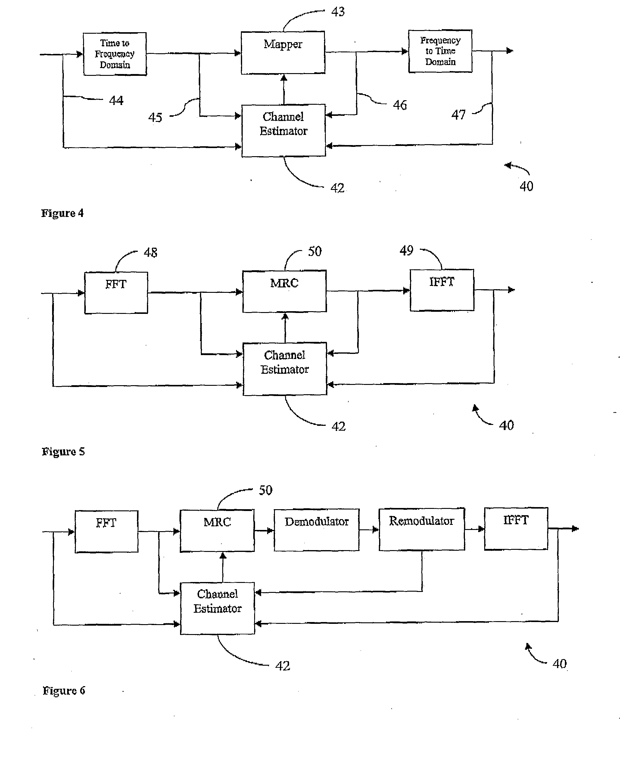
Methods and apparatus are described for improving receiver performance in a multicarrier communication network in which an encoded symbol (250) is transmitted over a transmission channel (20) in the communications system. A model of the transmission channel (20) is estimated (718, 760), said model characterising an effect of intercarrier interference on at least one carrier in the multicarrier system. The received symbol (250) is decoded (720, 762) using the estimated model to remove a predicted effect of intercarrier interference. A pre-processor (40) is also described for operation in conjunction with a communications receiver (30) in the network. The pre-processor (40) includes a channel estimator (42) operable to estimate at least one feature of the communication channel based on a received signal. The pre-processor (40) modifies the received signal dependent on the at least one estimated feature and provides the modified signal to the communications receiver (30).

Description

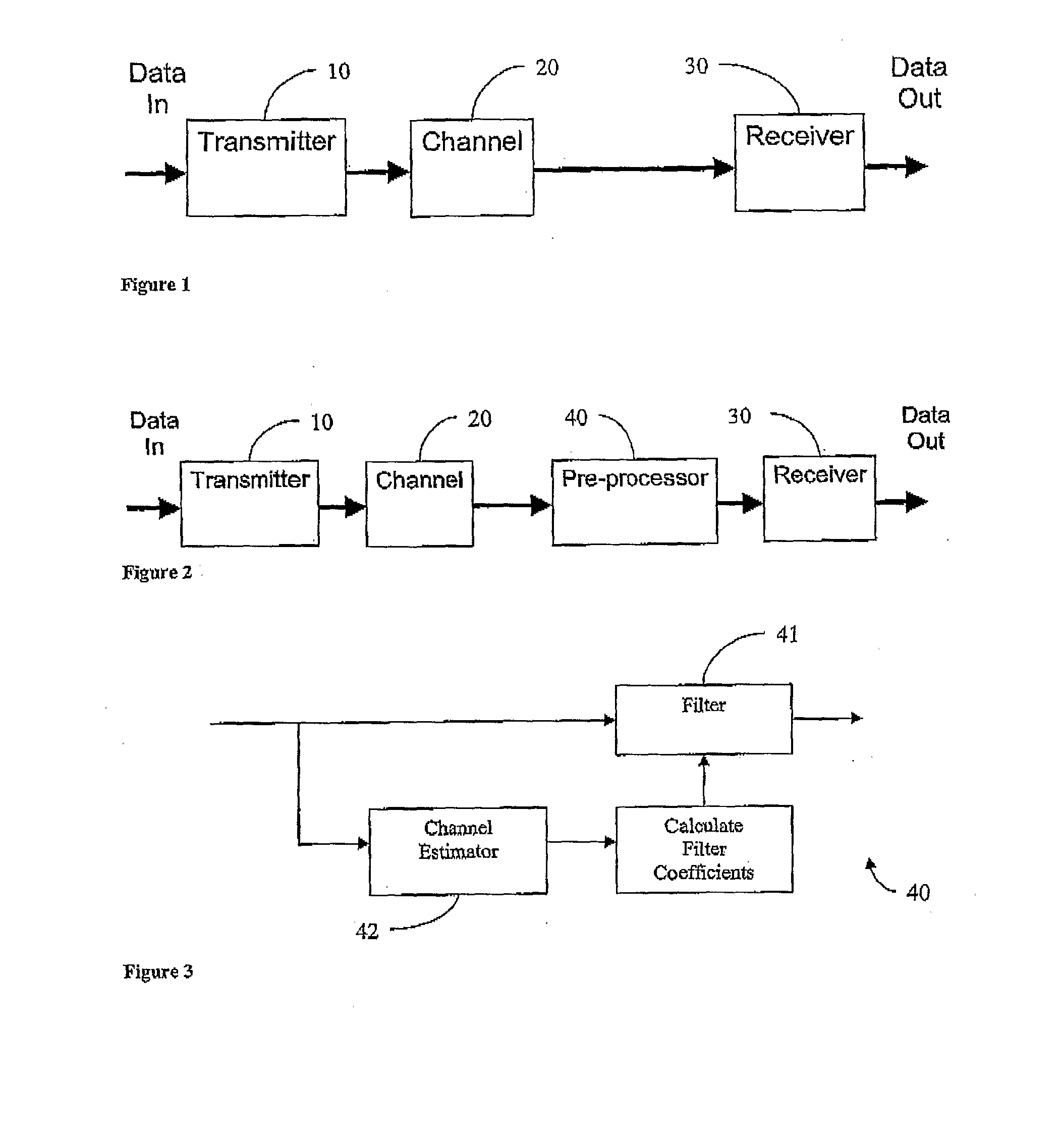
FIELD OF THE INVENTION[0001]The present invention relates to communication systems and, in particular, to enhancing the performance of receivers in a communication network.BACKGROUND OF THE INVENTION[0002]Communication systems may be modelled in terms of a transmitter 10 and receiver 30, separated by a channel 20, as shown in FIG. 1. The transmitter 10 transforms the data into a signal suitable for transmission over the channel 20. The channel may distort the transmitted signal in some way. The receiver's goal is to remove the effects of the channel distortions from the signal and to transform the signal into an estimate of the original data.[0003]The receiver may include a Channel Estimator. The Channel Estimator may observe a received signal that has been distorted by transmission over the channel, and generate a channel estimate based upon this observation. Channel distortions may include amplitude distortions, frequency offsets, phase offsets, Doppler effects, or distortions res...

Claims


Application Information

Patent Timeline
IPC IPC(8): H04B1/10H04W84/12H04L1/00
CPCH04L1/0045H04L1/0047H04L1/0059H04L27/2647H04L25/022H04L25/0224H04L25/03318H04L25/0204H04B1/10H04L1/20H04L1/0048H04L1/0054H04L25/0202
Inventor ALEXANDER, PAUL D.GRAY, PAUL K.HALEY, DAVID V.BUETEFUER, JOHN L.GRANT, ALEXANDER J.PHAM, PHUC N.SUTTON, JOSHUA C.SUTER, MARTIN
Owner COHDA WIRELESS
Learn More