Method and Apparatus for Sensing Channel Availability in Wireless Networks

a wireless network and channel availability technology, applied in the field of underwater optical transmission systems, can solve the problems of increasing the difficulty of detecting the availability of wireless networks

Active Publication Date: 2010-04-15
INTERDIGITAL CE PATENT HLDG
View PDF5 Cites 17 Cited by
  • Summary
  • Abstract
  • Description
  • Claims
  • Application Information

AI Technical Summary

Problems solved by technology

Over long distances the strength and quality of a transmitted optical signal diminishes.
Since the cables are relatively inaccessible on the ocean floor repair solutions can be complex and repair timelines and costs quite significant.
In this case the additional current traversing the repeaters leads to additional ohmic losses that can be problematic.

Method used


Image

  • Method and Apparatus for Sensing Channel Availability in Wireless Networks
  • Method and Apparatus for Sensing Channel Availability in Wireless Networks
  • Method and Apparatus for Sensing Channel Availability in Wireless Networks

Examples


Embodiment Construction

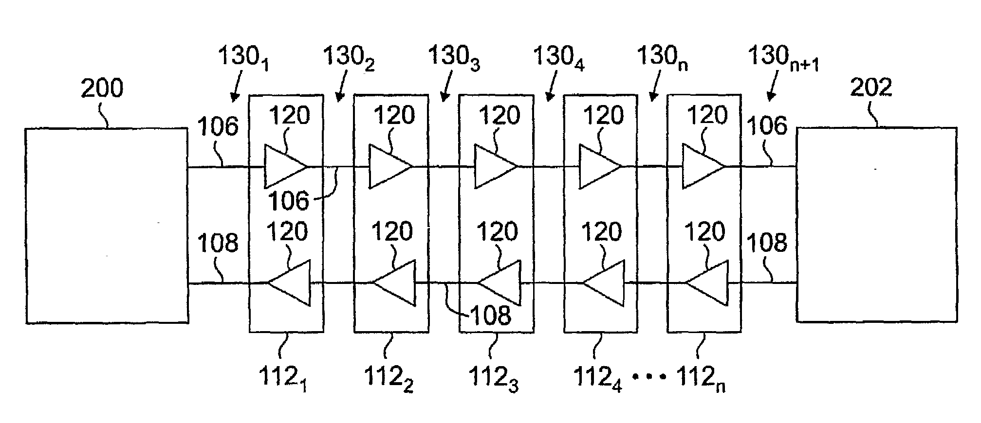
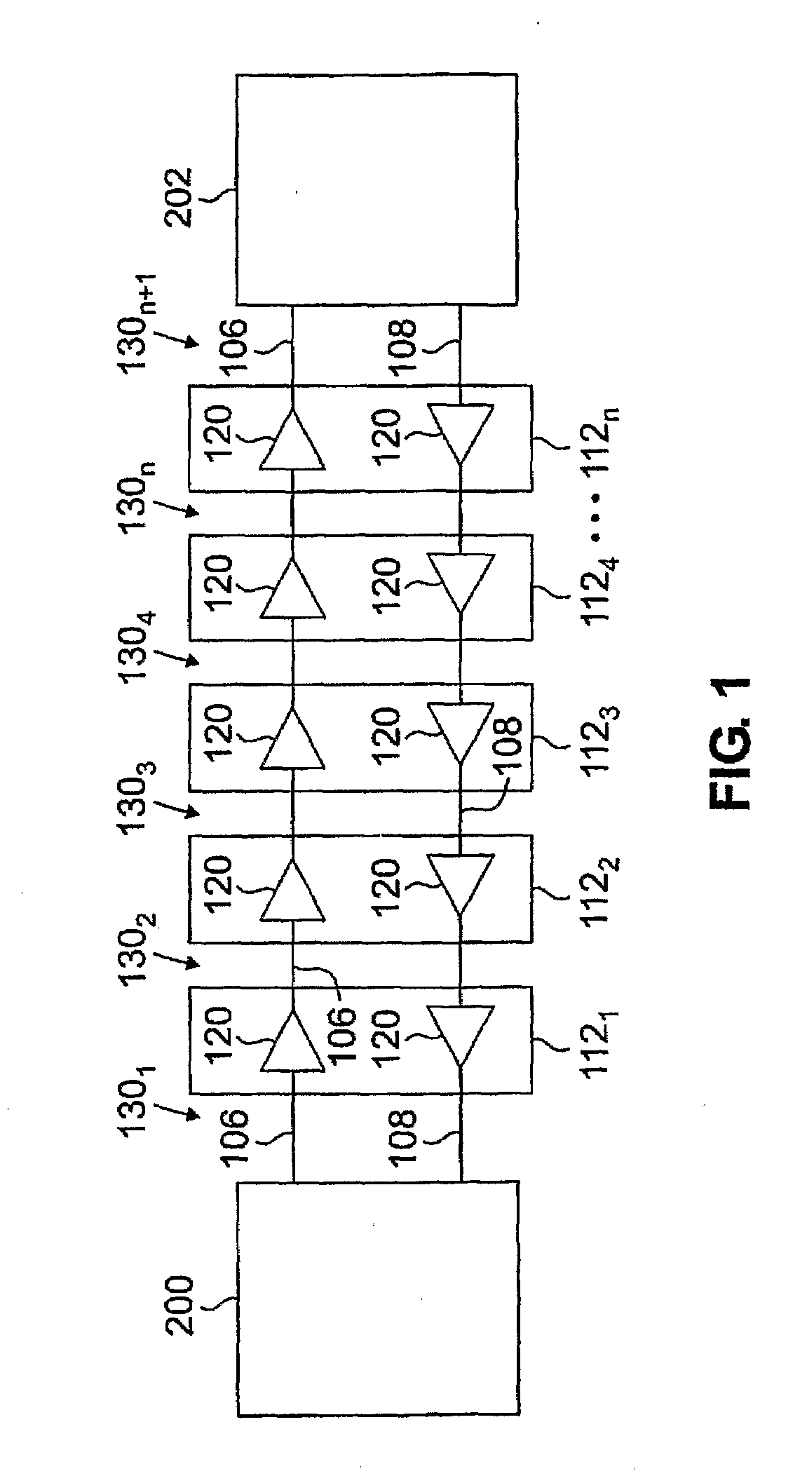
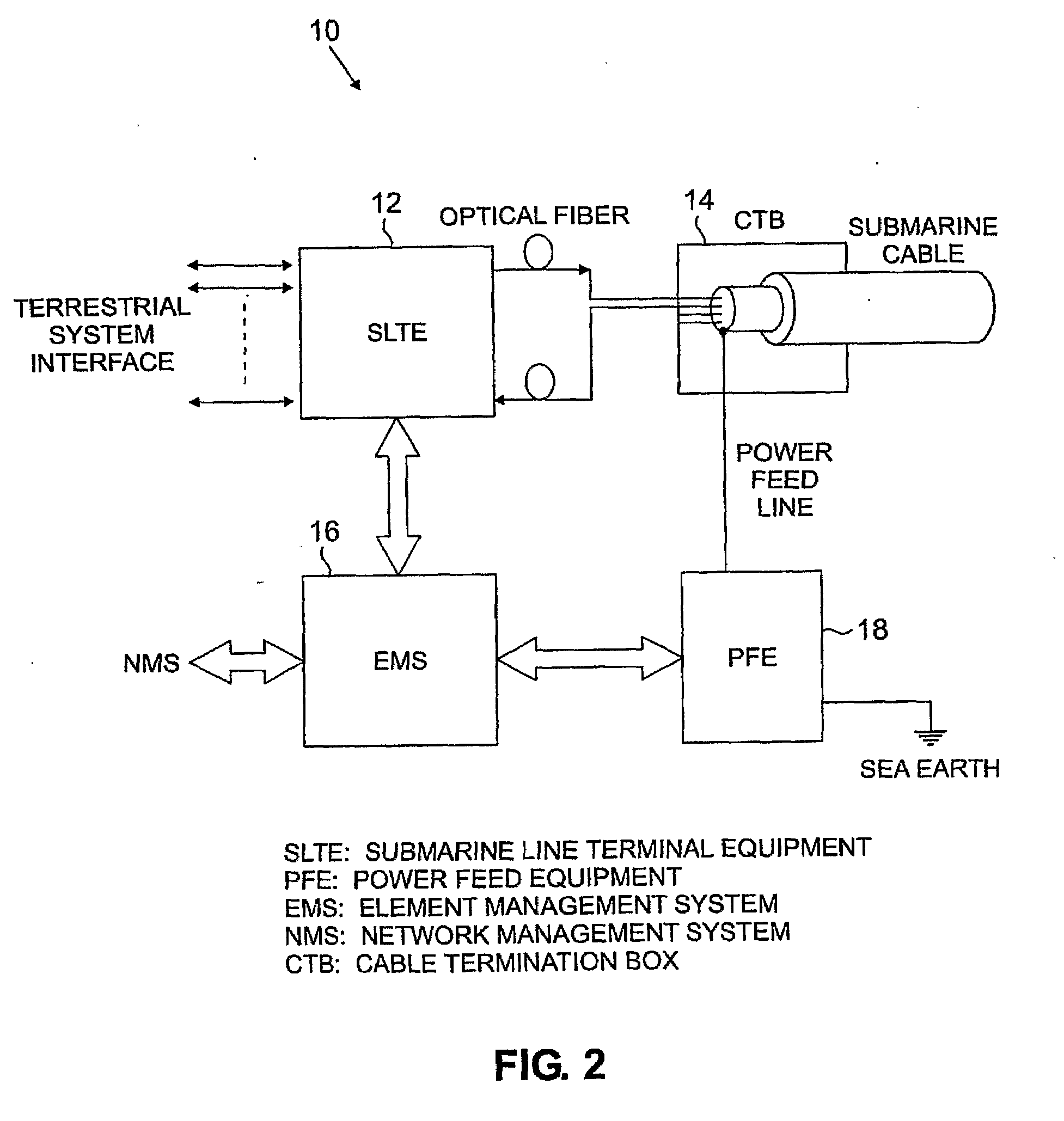
[0018]FIG. 1 shows a simplified block diagram of an exemplary wavelength division multiplexed (WDM) transmission system in which the present invention may be employed. The transmission system serves to transmit a plurality of optical channels over a pair of unidirectional optical fibers 106 and 108 between cable stations 200 and 202. Optical fibers 106 and 108 are housed in an optical cable that also includes a power conductor for supplying power to the repeaters. Cable stations 200 and 202 are of the type depicted in FIG. 2. The transmission path is segmented into transmission spans or links 1301, 1302, 1303, . . . 130n+1. The transmission spans 130, which are concatenated by repeaters 1121, 1122, . . . 112n, can range from 40 to 120 km in length, or even longer if Raman amplification is employed. The repeaters include optical amplifiers 120 that connect each of the spans 130. It should be noted that the invention is not limited to point-to-point network architectures such as shown...


PUM


Abstract

A method and apparatus is provided for applying an electroding tone to a power conductor located in an undersea optical cable employed in an undersea optical transmission system having at least one repeater. The method begins by applying a DC line current to the power conductor. The DC line current has a value sufficient to power the repeater and less than a value sufficient to power the repeater and to perform electroding. An AC current is impressed on the DC line current at a prescribed frequency and a peak-to-peak amplitude ranging from zero and a prescribed value to generate the tone. The impression or application of the AC current is terminated after a period of time at least sufficient to locate the optical cable or an optical cable fault.

Description

STATEMENT OF RELATED APPLICATIONS[0001]This application claims the benefit of U.S. Provisional Patent Application Ser. No. 60 / 658,321, filed Mar. 3, 2005, which is incorporated herein by reference in its entirety.FIELD OF THE INVENTION[0002]The present invention relates generally to undersea optical transmission systems, and more particularly to a cable station for an optical transmission system to which electrical power is supplied such as an undersea optical transmission system.BACKGROUND OF THE INVENTION[0003]An undersea or submarine optical transmission system consists of land-based cable stations interconnected by a cable that is installed on the ocean floor. The cable contains optical fibers that carry Dense Wavelength Division Multiplexed (DWDM) optical signals between the terminals. The cable stations contain power supplies for the undersea cable, transmission equipment to insert and remove DWDM signals from the fibers and associated monitoring and control equipment. Over lo...

Claims


Application Information

Patent Timeline
Patent Type & Authority Applications(United States)
IPC IPC(8): H04B10/16H04B10/29
CPCH04B2210/077H04B10/0771
Inventor LIU, HANGGAO, WEN
Owner INTERDIGITAL CE PATENT HLDG
Why Eureka
Try Eureka