Scroll compressor

a compressor and compressor technology, applied in the direction of machines/engines, rotary/oscillating piston pump components, liquid fuel engines, etc., to achieve the effect of improving compression efficiency, reducing gas leakage from the tip clearance, and improving compression efficiency

Active Publication Date: 2010-04-15
MITSUBISHI HEAVY IND LTD
View PDF2 Cites 8 Cited by
  • Summary
  • Abstract
  • Description
  • Claims
  • Application Information

AI Technical Summary

Benefits of technology

[0036]According to the thirteenth aspect of the present invention, the outer circumference side tip seal groove with respect to the step portion is stepwise or continuously made gradually deeper toward the center side of the spiral wrap, and the height difference ε1 is made gradually larger from the outer circumference side to the inner circumference of the spiral wrap toward the center side. In a manner to match the fact that the inner circumference side tip seal groove with respect to the step portion is stepwise and continuously made gradually deeper toward the center side of the spiral wrap, the spiral wrap is stepwise or continuously made gradually lower toward the center side of the spiral wrap. The gradient Eg at the time when the inner circumference side tip seal groove is stepwise or continuously made gradually deeper toward the center side and the gradient Er at the time when the spiral wrap is stepwise or continuously made gradually lower toward the center side are made to have the relation of Eg>Er. In a manner to match a relatively small temperature gradient on the outer circumference side and a relatively high temperature gradient on the inner circumference side, therefore, the tip clearances in operation on the outer circumference side and the inner circumference side of the spiral wraps can be optimized to match the individual temperature gradients and can be made as small as possible.
[0037]As a result, the gas leakage from the tip clearances in the whole range from the intake to the discharge can be reduced to improve the compression efficiency.
[0038]In a manner to match the continuous temperature gradient from the intake to the discharge, according to the present invention, the tip clearance in operation in the spiral direction of the spiral wrap can be optimized and reduced. As a result, the gas leakage from the tip clearance can be reduced to improve the compression efficiency thereby to realize a high performance.

Problems solved by technology

In connection with the influences by the thermal expansion, however, the scroll compressors of the aforementioned Patent Documents have found it difficult to follow the continuous temperature gradient from an intake temperature to a discharge temperature and still insufficient to optimize the tip clearance in a manner to match the temperature gradient thereby to improve the compression performance.

Method used


Image

  • Scroll compressor
  • Scroll compressor
  • Scroll compressor

Examples


first embodiment

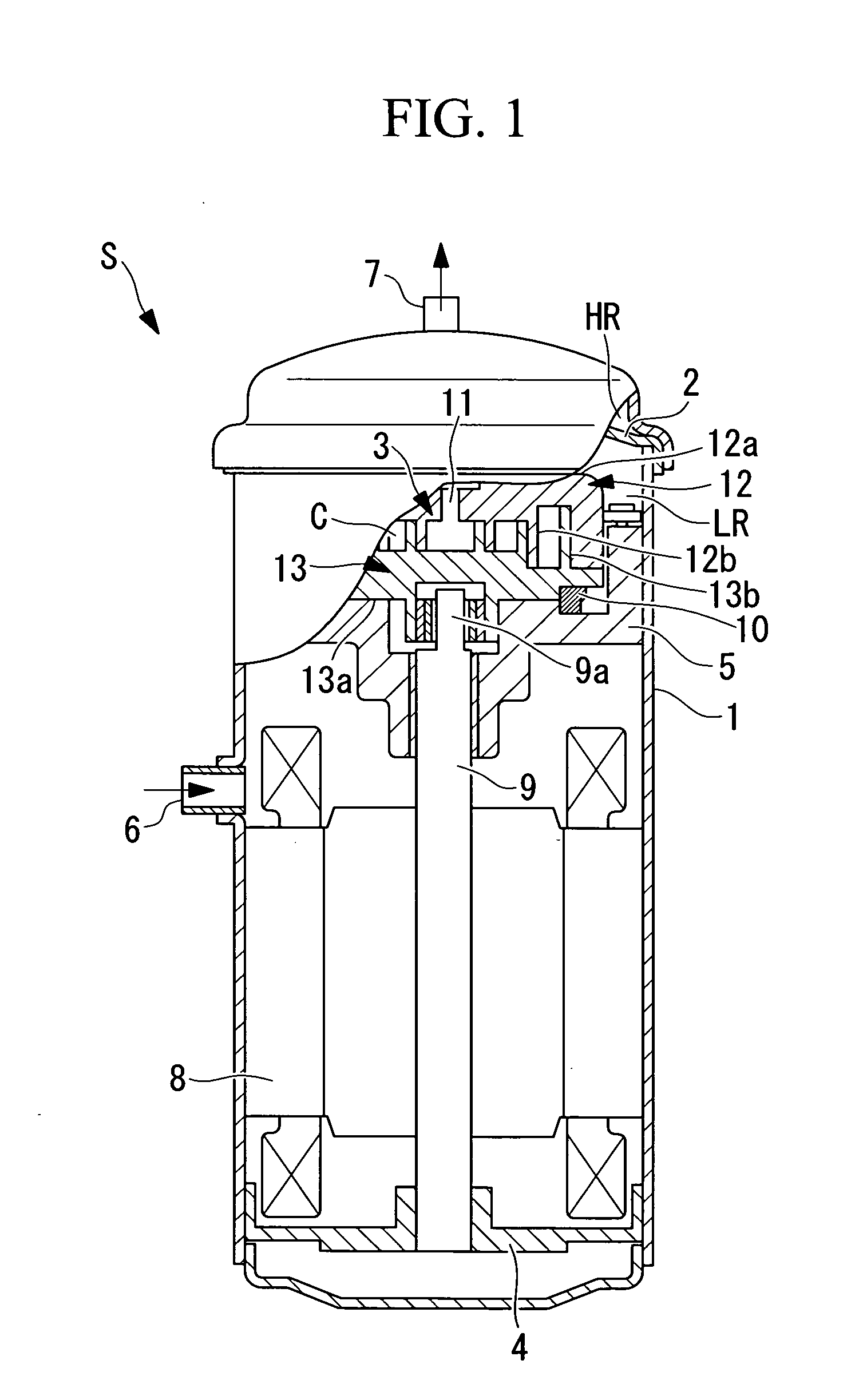
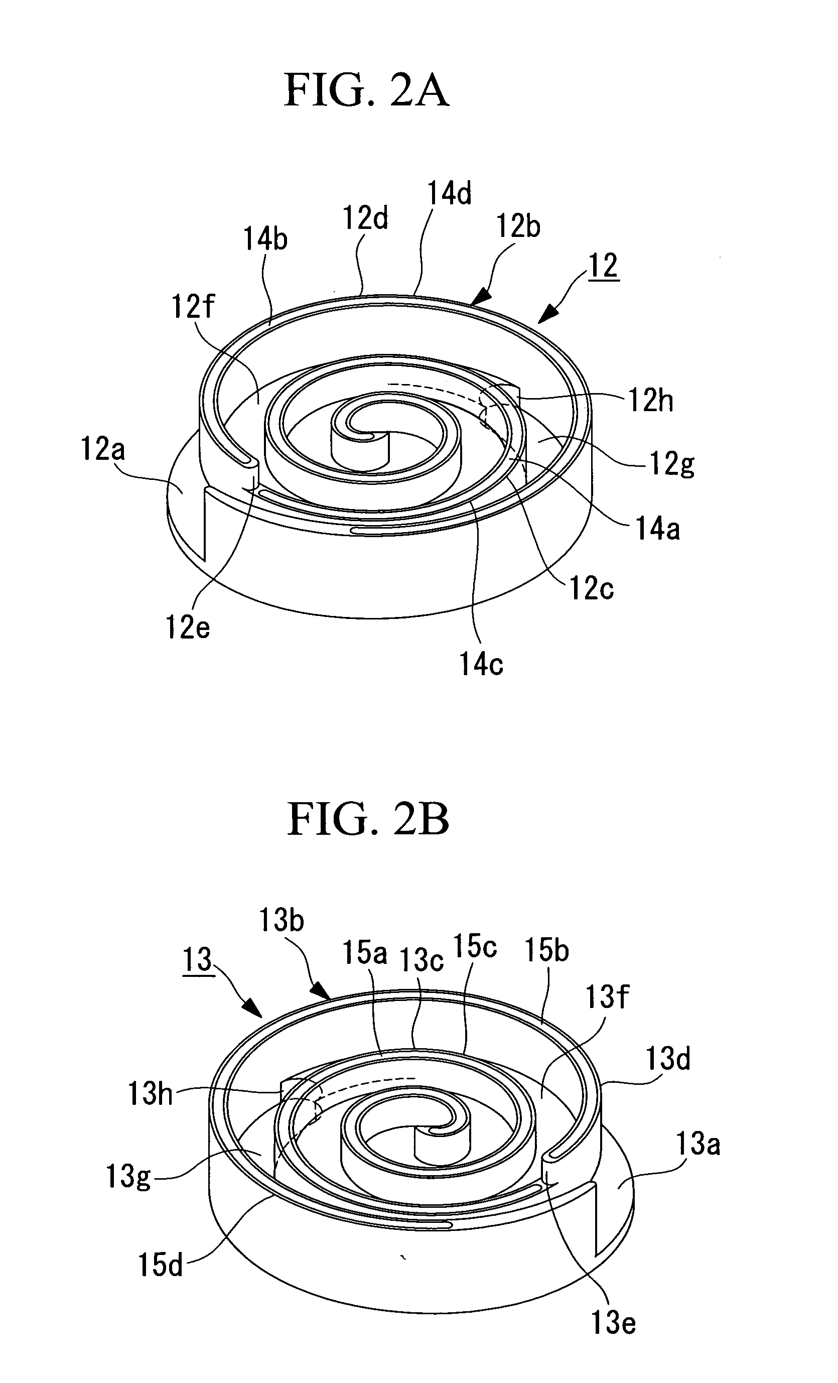
[0069]In the following, a first embodiment of the present invention is described with reference to FIG. 1 to FIG. 4.

[0070]FIG. 1 shows a partially sectional, longitudinal view of a scroll compressor S. This scroll compressor S is a sealed type scroll compressor S having a sealed housing 1. This sealed housing 1 is equipped therein with a discharge cover 2 for separating the inside of the sealed housing 1 into a high-pressure chamber HR and a low-pressure chamber LR. The side of the low-pressure chamber LR is equipped with a compression mechanism 3 and an electric motor 8, and is connected to an intake pipe 6. On the other hand, the side of the high-pressure chamber HR is connected with a discharge pipe 7.

[0071]The compression mechanism 3 is mounted on a frame 5, which is fixed in the sealed housing 1 in the low-pressure chamber LR. This compression mechanism 3 is connected to the electric motor 8 by a crankshaft 9, which is supported through a bearing (not shown) on the frame 5 and ...

second embodiment

[0096]Next, a second embodiment of the present invention is described with reference to FIG. 5.

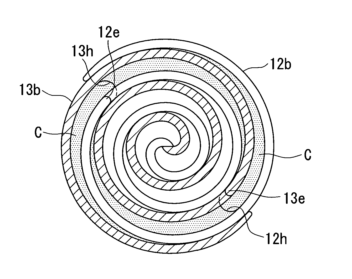
[0097]The present embodiment is different from the aforementioned first embodiment in how the heights (or the wrap heights) of the leading end faces of the spiral wraps 12b and 13b are stepwise varied. The remaining points are similar to those of the first embodiment so that their descriptions are omitted.

[0098]In the aforementioned first embodiment, the leading end faces 12c and 12d and the leading end faces 13c and 13d are stepwise varied in heights individually with constant height differences δo and δi (δo=δi). In the present embodiment, however, the height difference SU between the leading end faces 12c and 13c on the inner circumference side is made larger than the height difference δo (δo1) between the leading end faces 12d and 13d on the outer circumference side of the step portions 12e and 13e of the individual spiral wraps 12b and 13b.

[0099]The height difference δi1 of the leadi...

third embodiment

[0101]Next, a third embodiment of the present invention is described with reference to FIG. 6.

[0102]The present embodiment is different from the aforementioned first and second embodiments in how the heights (wrap heights) of the leading end faces of the spiral wraps 12b and 13b are stepwise varied. The remaining points are similar to those of the first and second embodiments so that their descriptions are omitted.

[0103]In the present embodiment, the leading end faces 12d and 13d on the outer circumference side are stepwise varied in heights at a constant height difference δo, but the leading end faces 12c and 13c on the inner circumference side are gradually made larger at height differences δi2, δi3 and δiN (δi23<δiN) toward the center side.

[0104]As described above, the height differences δi2, δi3 and δiN (δi2312c and 13c on the inner circumference side are gradually made larger toward the center side, so that the gradient (Ei) at the time when the heights of the leading end faces...


PUM


Abstract

Intended is to provide a scroll compressor capable of performing three-dimensional compressions, which can optimize a tip clearance in operation while considering a thermal expansion and a pressure deformation and which can reduce a compression leakage to improve a compression efficiency thereby to realize a high performance. The leading end faces (13c and 13d) and the bottom face of a spiral wrap (13b) have a step portion (13e), and the wrap height on the outer circumference side of the spiral wrap (13b) is made larger than that on the inner circumference side wrap height, so that the scroll compressor can perform three-dimensional compressions capable of compressing in the circumferential direction of the spiral wrap (13b) and in the wrap height direction. The spiral wrap (13b) on the inner circumference side with respect to the step portion (13e) is stepwise or continuously made gradually lower toward the center side of the spiral wrap (13b), and the tip clearance (Δi) of the spiral wrap on the inner circumference side with respect to the step portion (13) is made gradually larger toward the center side of the spiral wrap (13b).

Description

TECHNICAL FIELD[0001]The present invention relates to a scroll compressor, in which the outer circumference side wrap of spiral wraps of a scroll member is set higher than the inner circumference side wrap so that it can perform three-dimensional compressions, which can perform compression in the circumferential direction of the spiral wraps and in the wrap height direction.BACKGROUND ART[0002]In recent years, there has been developed a scroll compressor which includes a fixed scroll member having a fixed spiral wrap erected on one face of a fixed end plate, and an orbiting scroll member having an orbiting spiral wrap erected on one face of an orbiting end plate and assembled in a manner capable of orbiting, while being blocked from rotation, with respect to the fixed scroll member. The fixed scroll member and the orbiting scroll member individually include step portions on the leading end faces and the bottom faces of their individual spiral wraps such that the spiral wraps have a ...

Claims


Application Information

Patent Timeline
Patent Type & Authority Applications(United States)
IPC IPC(8): F04C18/02
CPCF04C18/0215F04C27/007F04C23/008F04C18/0276
Inventor SATO, HAJIMETATEISHI, TAICHIKIMATA, YOSHIYUKIMIYAMOTO, YOSHIAKITAKASU, YOGO
Owner MITSUBISHI HEAVY IND LTD
Why Eureka
Try Eureka