
Terminal unit and method of manufacturing the same

a terminal unit and terminal technology, applied in the field of terminal units, can solve problems such as unfavorable electrical conductivity, and achieve the effect of preventing the variation of electric conductivity in the terminal uni

Active Publication Date: 2010-04-15
TOYOTA JIDOSHA KK
View PDF1 Cites 21 Cited by
  • Summary
  • Abstract
  • Description
  • Claims
  • Application Information

AI Technical Summary

Benefits of technology

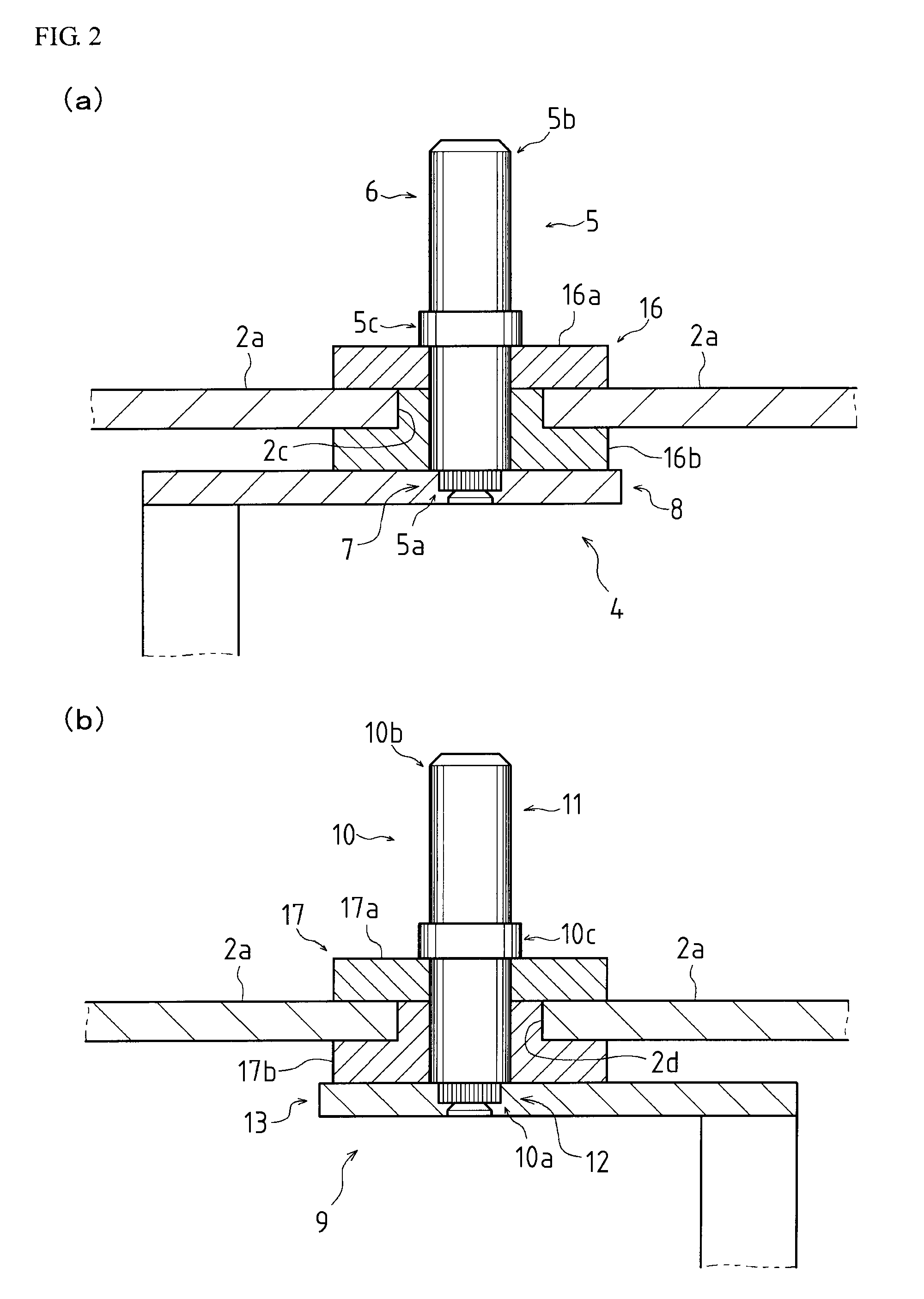
[0006]The present invention relates to a technique of a terminal unit having a press fitting structure of a terminal part into an electrode part and aims to provide a terminal unit capable of preventing a vary in electrical conductivity thereof by means of fixing the terminal part to the electrode part with removing the oxide films formed on the parts.
[0010]Therefore, the electric conductivity between the terminal part and the electrode part is secured, thereby preventing varying in quality of the electric products with the terminal unit.
[0014]Accordingly, the uneven surface of the insert portion enlarges the contacting area between the terminal part and the electrode part, thereby enhancing the electric conductivity thereof. Furthermore, the neck portion of the tapered portion receives the materials pared off by the uneven surface in press fitting. As a result, the generation of the chips in press fitting is prevented.
[0018]Therefore, the electric conductivity between the terminal part and the electrode part is secured, thereby preventing varying in quality of the electric products with the terminal unit.
[0022]Accordingly, the uneven surface of the insert portion enlarges the contacting area between the terminal part and the electrode part, thereby enhancing the electric conductivity thereof. Furthermore, the neck portion of the tapered portion receives the materials pared off by the uneven surface in press fitting. As a result, the generation of the chips in press fitting is prevented.
[0023]According to the present invention, the varying of electric conductivity in the terminal unit is prevented.

Problems solved by technology

Unfortunately, the unevenness of the electrical conductivity occurs depending on the condition of press fitting or crimping.

Method used


Image

  • Terminal unit and method of manufacturing the same
  • Terminal unit and method of manufacturing the same
  • Terminal unit and method of manufacturing the same

Examples


Embodiment Construction

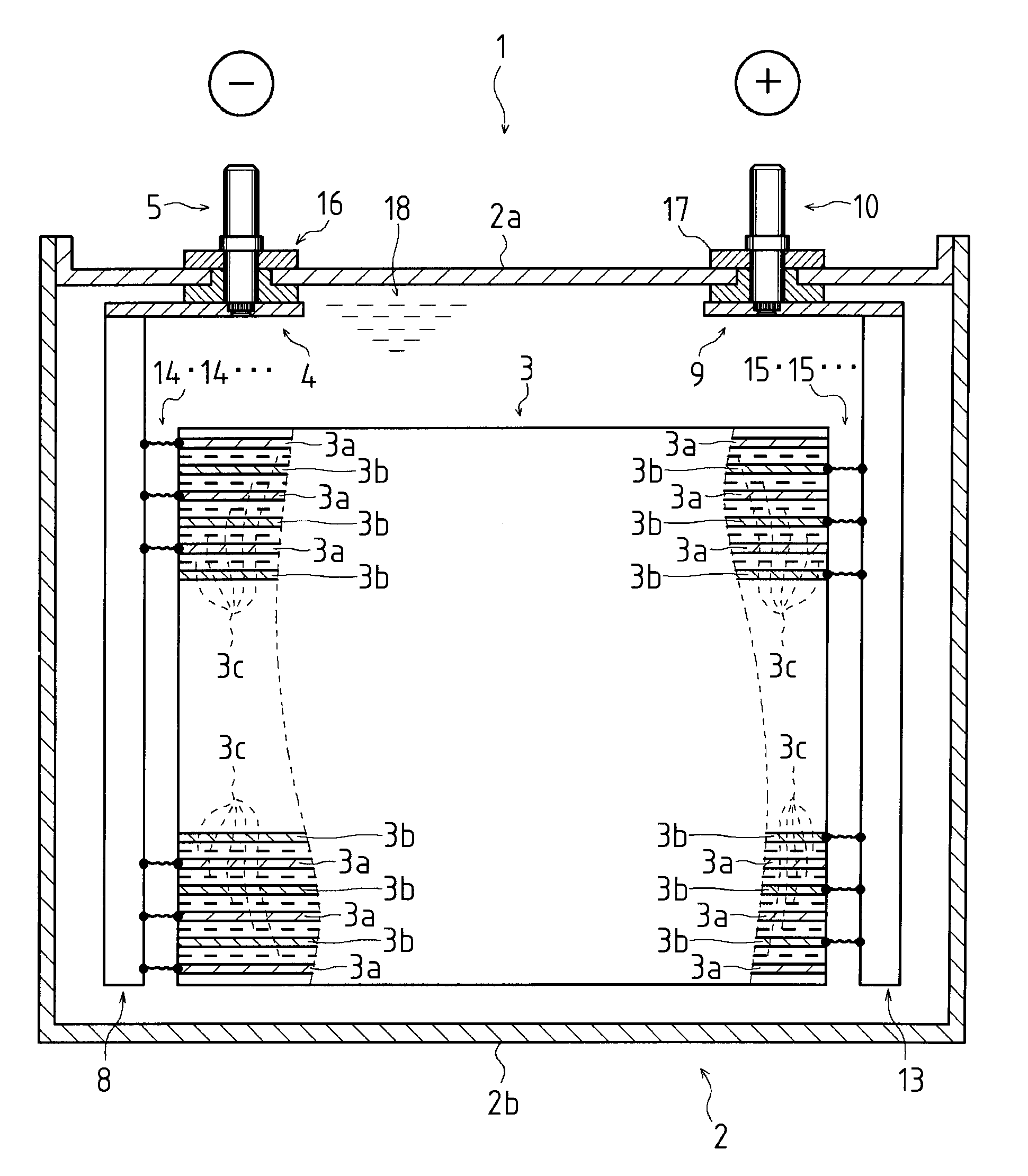
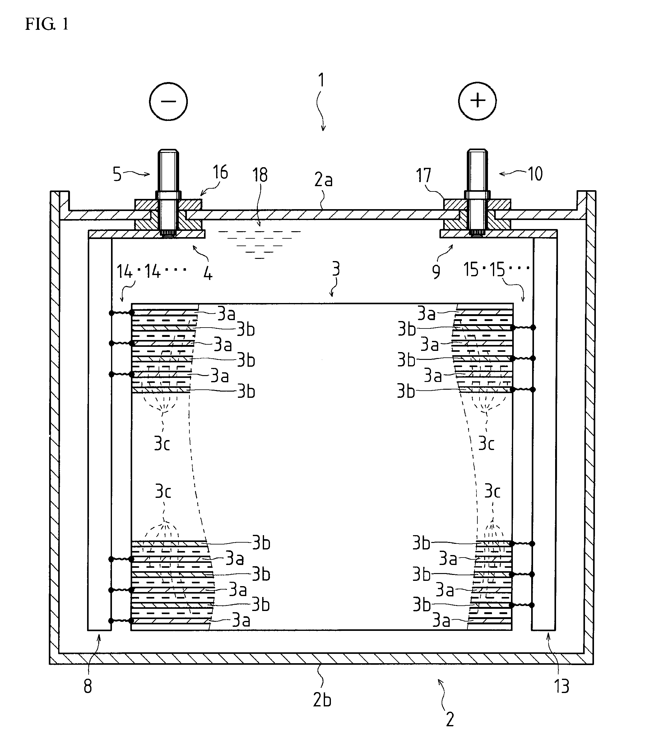
[0032]Referring FIG. 1, the whole structure of a battery 1 will be described, which includes terminal units 4, 9, each of which is one embodiment of a terminal unit according to the present invention.

[0033]It should be noted that the battery 1 including the terminal units 4, 9 is described in this description, though the terminal unit according to the present invention may be broadly applied, not limited to the battery.

[0034]As shown in FIG. 1, the battery 1 is a box-shaped lithium-ion battery, containing a case 2, an electrode body 3, and the terminal units 4, 9.

[0035]The case 2 is composed of a lid part 2a and a case part 2b, and is filled with an electrolyte solution 18 that behave as an electrically conductive medium.

[0036]The electrode body 3 is, for example, composed of a negative electrode sheet 3a such as a copper sheet coated with a carbon substance, a positive electrode sheet 3b such as a aluminum sheet coated with a lithium-ion compound and a separator sheet 3c, and the s...


PUM

PropertyMeasurementUnit
diameters D1aaaaaaaaaa
heights H1aaaaaaaaaa
diameters D2aaaaaaaaaa

Abstract

The first aspect of the present invention is a terminal unit which contains an electrode part disposed in a case, for connecting with an electrode body and a terminal part having a rod shape with a first end and a second end, the first end for fixing to the electrode part, and the second end extending outside of the case. In one embodiment of the first aspect of the invention, the electrode part includes an insert hole into which the terminal part is inserted, the terminal part comprises an insert portion having an insert portion having a larger diameter than that of the hole and formed at the first end and a tip portion having a smaller diameter than that of the hole and formed at the nearer side of the first end than the insert portion. And, the clinch portion is press fitted into the insert hole, thereby fixing the terminal part to the electrode part. According to the present invention, the varying of electric conductivity in the terminal unit is prevented.

Description

BACKGROUND OF THE INVENTION[0001]1. Field of the Invention[0002]The present invention relates to a terminal unit and a method of manufacturing the terminal unit.[0003]2. Description of Related Art[0004]Conventionally, to press fit terminal parts of rod shape into holes formed on electrode parts such as current collection plates, or to crimp terminal parts after inserting the terminal parts into holes of electrode parts provides terminal units with fixing structure of the terminal parts to the electrode parts, and batteries equipped with the terminal units having the fixing structures are well known (e.g. see JP 2005-285406 A).[0005]JP 2005-285406 A discloses a conventional terminal unit, in which the metal oxide films formed on each surface of the parts surrounds the contacting area of the terminal part to the electrode part. Unfortunately, the unevenness of the electrical conductivity occurs depending on the condition of press fitting or crimping. Therefore, the batteries including...

Claims


Application Information

Patent Timeline
Patent Type & Authority Applications(United States)
IPC IPC(8): H01M2/30H01M2/00H01M50/55H01M50/553
CPCH01M2/021Y10T29/49108H01M10/0525H01M2/30Y02E60/10H01M50/55H01M50/553
Inventor TAKASHIRO, SHIGERUKADO, HIROYASUISHII, SHIGEKI
Owner TOYOTA JIDOSHA KK
Learn More