Arbitrary shaping of temporal noise envelope without side-information

Active Publication Date: 2010-04-15
DOLBY LAB LICENSING CORP
View PDF8 Cites 30 Cited by
  • Summary
  • Abstract
  • Description
  • Claims
  • Application Information

AI Technical Summary

Benefits of technology

[0033]Another benefit of the present invention is that the feedback filter may be changed throughout the spectrum such that the temporal progression of noise may be better matched to the signal characteristics of a spectral group. In other words, a unique feedback filter may be employed for each of one or more frequency bins or groups of frequency bins, a frequency bin constituting a spectral group. Although TNS can also provide such ability, the need to transmit filter coefficients to the decoder as well as the need to indicate the desired spectral group to the decoder significantly limits the number of spectral regions that can be used.

Problems solved by technology

However, TNS has some limitations.
These requirements lead to the following limitations:1. Increased bit rate consumption in order to transmit the filter coefficients2. The need to apply the inverse filter to the spectrum means that TNS cannot provide backward compatibility to existing systems such as AC-3 (see reference 4, below).3. Increased decoder complexity due to the need to apply the inverse filter to the spectrum

Method used


Image

  • Arbitrary shaping of temporal noise envelope without side-information
  • Arbitrary shaping of temporal noise envelope without side-information
  • Arbitrary shaping of temporal noise envelope without side-information

Examples


Embodiment Construction

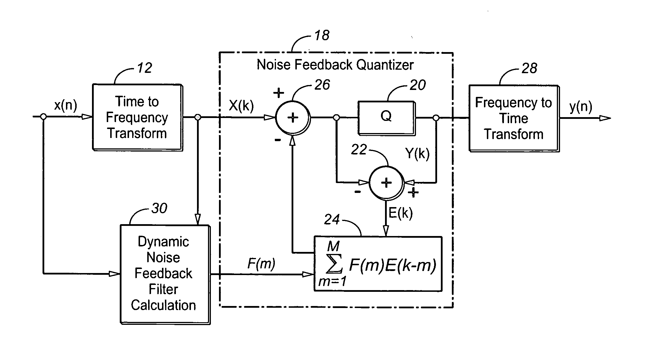
Spectral Domain Noise Feedback Quantization (NFQ)

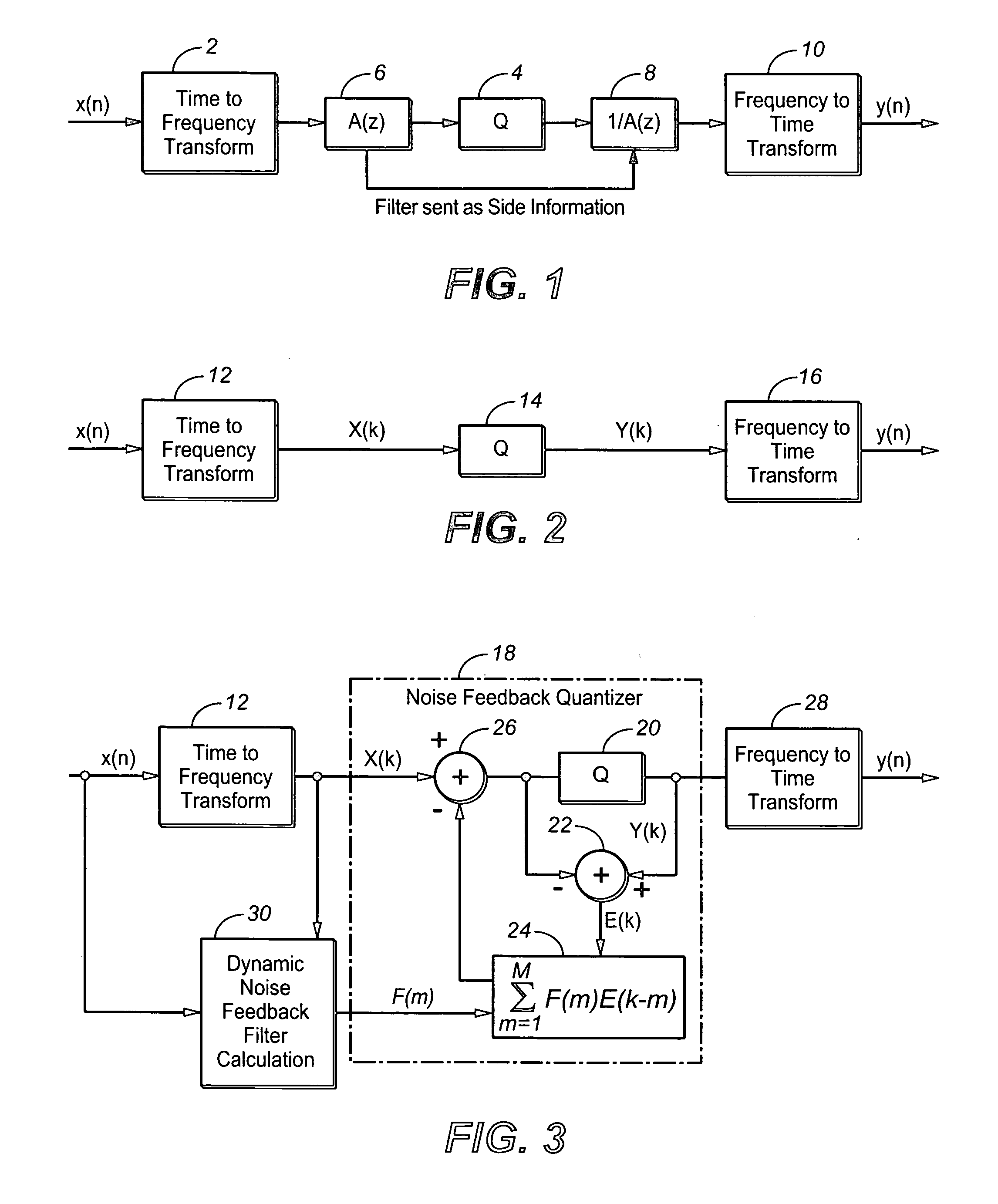
[0034]Most modern audio coding techniques, including AAC (see reference 2, below) and AC-3 (see reference 4, below), perform quantization in the spectral domain in order to control, in a perceptually relevant way, the noise introduced by quantization. Typically, the input time waveform is converted to the spectral domain using a time-frequency transform such as the MDCT. In parallel to the time-frequency transformation a perceptual model is calculated, which is then used to control the quantization noise occurring in each of the output coefficients of the time-frequency transform. FIG. 2 is a schematic block diagram showing a simplification of a prior art modern audio coding system (encoder and decoder) in which the input is converted to the spectral domain and the spectral representation of the signal is then quantized. A discrete time-domain signal x(n) is applied to a time-to-frequency transform or transform function (“Time to Freq...


PUM


Abstract

In a first aspect, arbitrary shaping of the temporal envelope of noise is provided in spectral domain coding systems without the need of side-information. In the encoding, a filtered measure of quantization error is applied as a feedback signal to the frequency-domain representation of a discrete time-domain signal prior to quantization, so that the filtering parameters of said filtering affect the shaping of quantization noise in the time domain of the quantized frequency-domain representation of the discrete time-domain signal when it is inversely transformed from the frequency domain back to the time domain in decoding. This may be accomplished with respect to each of a plurality of frequency bins or groups of bins. In another aspect, frequency-domain noise-feedback quantizing in digital audio encoding is provided.

Description

TECHNICAL FIELD [0001]The invention relates to digital audio coding. In particular, aspects of the invention relate to a digital audio encoding method; a digital audio decoder adapted to decode a bitstream generated by said digital audio encoding method; a digital audio decoding method; a method for frequency-domain noise-feedback quantizing in a digital audio encoder, apparatus for performing any of such methods; a computer program, stored on a computer-readable medium, for causing a computer to control such apparatus or to perform such methods; and a frequency-domain noise-feedback quantizer for use in a digital audio encoder.BACKGROUND ART [0002]The trade-off between time and frequency in spectral domain audio coding systems has lead to several techniques to ensure high audio coding performance while minimizing audible coding errors. Such techniques include block switching and Temporal Noise Shaping (TNS) (see reference 1, below), both of which are employed in MPEG-2 / 4 AAC (“AAC”...

Claims


Application Information

Patent Timeline
IPC IPC(8): G10L19/00
CPCG10L19/032H04B1/665G10L19/03G10L19/008
Inventor VINTON, MARK STUART
Owner DOLBY LAB LICENSING CORP
Why Eureka
Try Eureka