Articulating measuring arm with laser scanner

a technology of laser scanning and articulating measuring arms, which is applied in the direction of measuring devices, mechanical measuring arrangements, instruments, etc., can solve the problems and achieve the effect of less accurate laser scanning performance and easy removal and replacemen

Active Publication Date: 2010-04-22
HEXAGON METROLOGY INC
View PDF98 Cites 166 Cited by
  • Summary
  • Abstract
  • Description
  • Claims
  • Application Information

AI Technical Summary

Benefits of technology

[0008]One aspect of the present invention is the realization that such prior art systems suffer from a number of inefficiencies. For example, prior art systems typically require a repeatable kinematic mount that would allow the laser scanner to be easily removed and replaced from the arm. Such mounts are generic so that many different types of scanners can be mounted to the same CMM. These generic mounts place the laser scanner in non-optimal locations which results in less accurate laser scanning performance The various locations that existed for mounting the laser scanning box were on top of the last axis, forward and below the last axis, or off to the side of the last axis, as discussed further below.

Problems solved by technology

These generic mounts place the laser scanner in non-optimal locations which results in less accurate laser scanning performance The various locations that existed for mounting the laser scanning box were on top of the last axis, forward and below the last axis, or off to the side of the last axis, as discussed further below.

Method used


Image

  • Articulating measuring arm with laser scanner
  • Articulating measuring arm with laser scanner
  • Articulating measuring arm with laser scanner

Examples


Embodiment Construction

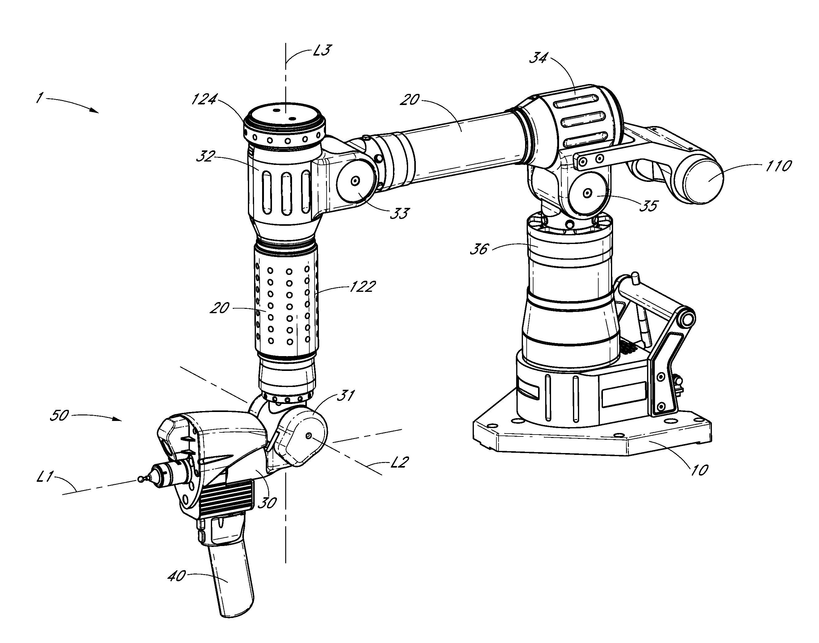
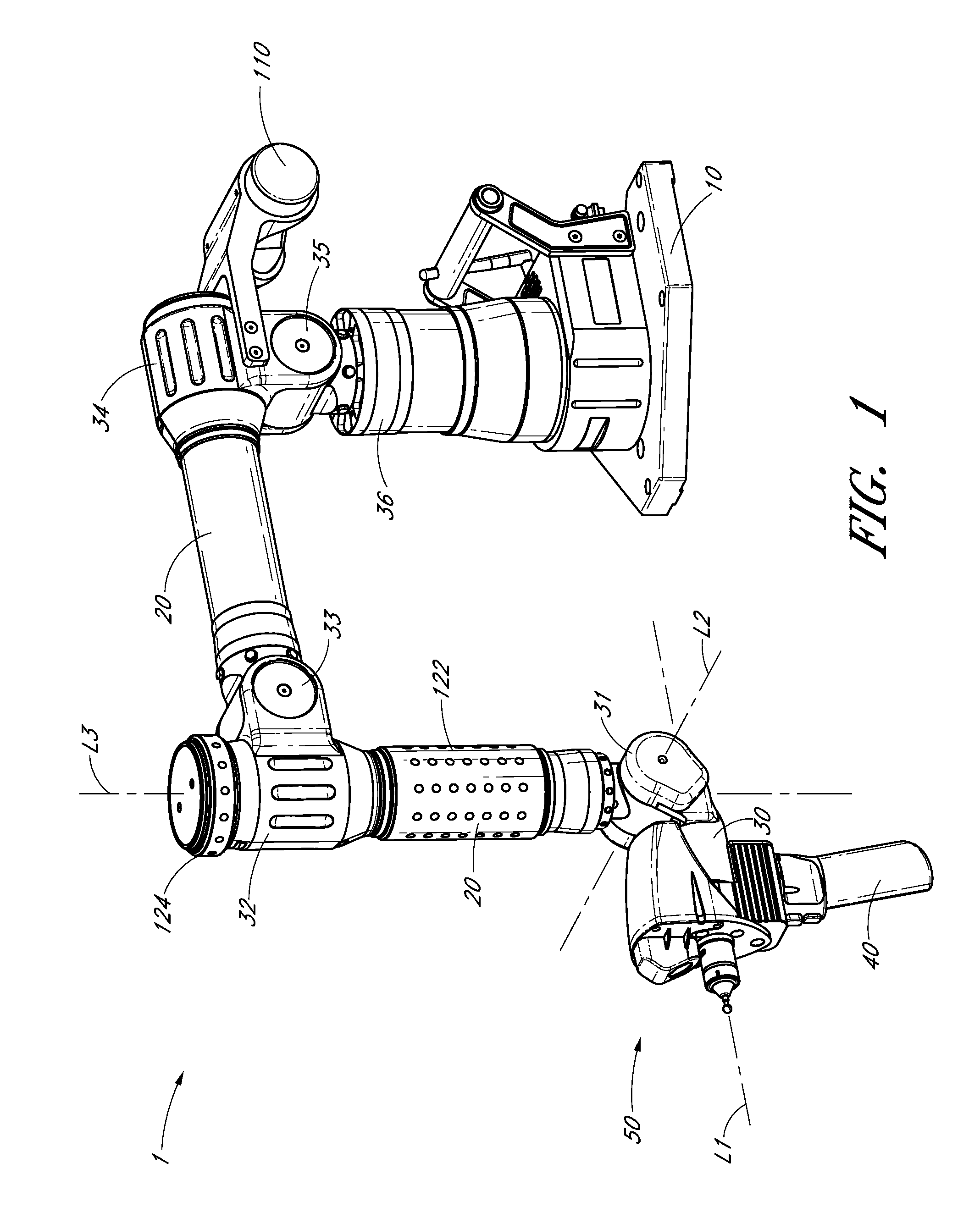
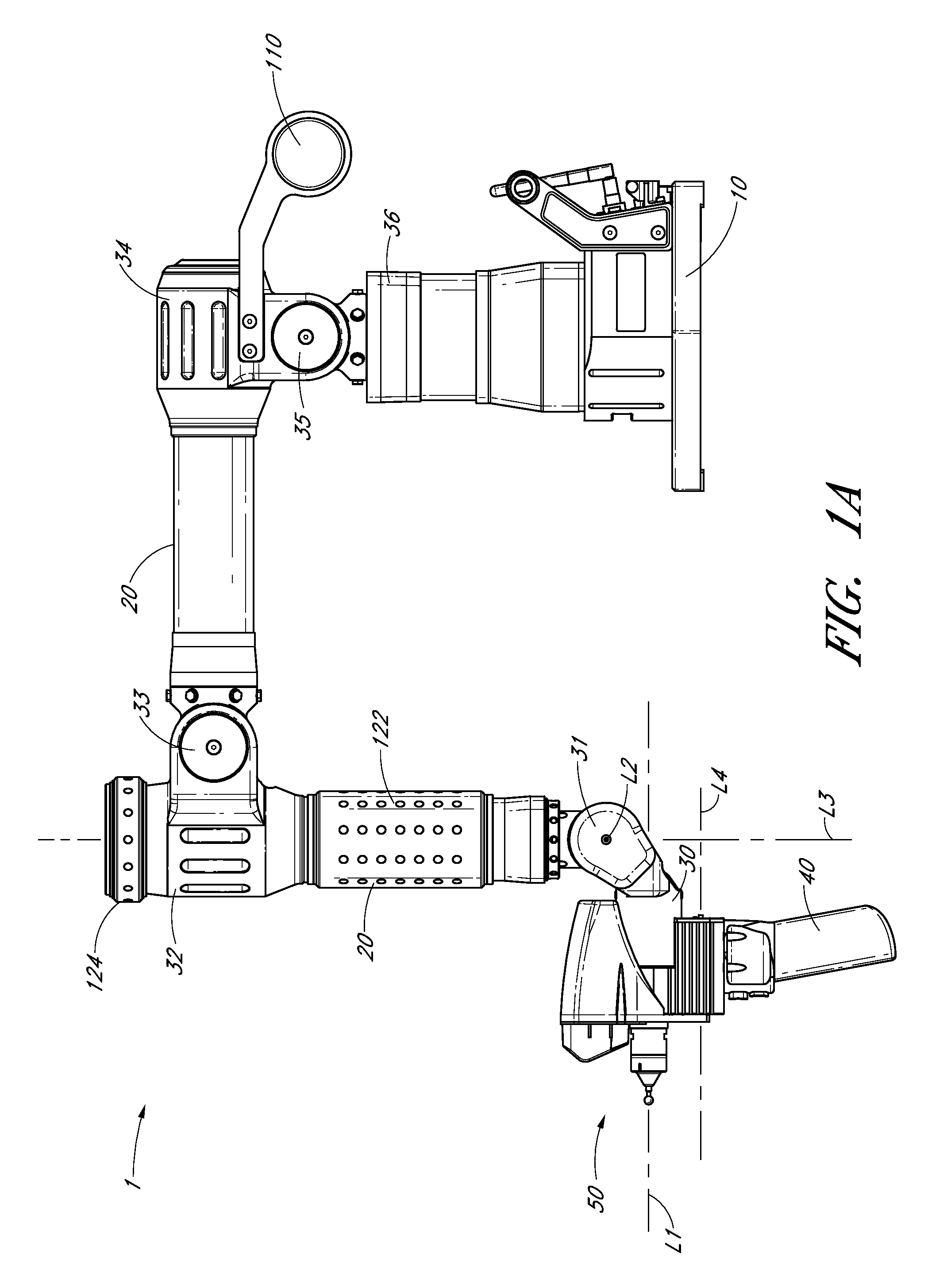
[0034]FIGS. 1-1B illustrate one embodiment of a portable coordinate measuring machine (PCMM) 1 in accordance with the present invention. In the illustrated embodiment, the PCMM 1 comprises a base 10, a plurality of rigid transfer members 20, a coordinate acquisition member 50 and a plurality of articulation members 30-36 connecting the rigid transfer members 20 to one another. Each articulation member 30-36 is configured to impart one or more rotational and / or angular degrees of freedom. Through the various articulation members 30-36, the PCMM 1 can be aligned in various spatial orientations thereby allowing fine positioning and orientating of the coordinate acquisition member 50 in three dimensional space.

[0035]The position of the rigid transfer members 20 and the coordinate acquisition member 50 may be adjusted using manual, robotic, semi-robotic and / or any other adjustment method. In one embodiment, the PCMM 1, through the various articulation members 30, is provided with seven r...


PUM


Abstract

A coordinate measurement device comprises an articulated arm having a first end, a second end, and a plurality of jointed arm segments therebetween. Each arm segment defines at least one axis of rotation. A laser scanner assembly is coupled to the second end of the arm and is rotatable about a last axis of rotation of the articulated arm. The laser scanner assembly comprises a laser and an image sensor. The laser is positioned on an opposite side of the last axis of rotation from the image sensor.

Description

PRIORITY INFORMATION[0001]This application claims the priority benefit under 35 U.S.C. §119(e) to U.S. Provisional Patent Application Ser. No. 61 / 106,096 (filed Oct. 16, 2008), the entirety of which is hereby expressly incorporated by reference herein.BACKGROUND OF THE INVENTION[0002]1. Field of the Invention[0003]The present invention relates to coordinate measurement machines and, more particularly, to coordinate measurement machines with laser scanners.[0004]2. Description of the Related Art[0005]Rectilinear measuring systems, also referred to as coordinate measuring machines (CMMs) and articulated arm measuring machines, are used to generate highly accurate geometry information. In general, these instruments capture the structural characteristics of an object for use in quality control, electronic rendering and / or duplication. One example of a conventional apparatus used for coordinate data acquisition is a portable coordinate measuring machine (PCMM), which is a portable device...

Claims


Application Information

Patent Timeline
Patent Type & Authority Applications(United States)
IPC IPC(8): G01B5/004G01B11/14
CPCG01B5/012Y10S33/21G01B11/022G01B11/007
Inventor FERRARI, PAUL
Owner HEXAGON METROLOGY INC
Why Eureka
Try Eureka