Dual wall structure for use in a combustor of a gas turbine engine

a gas turbine engine and wall structure technology, applied in the direction of machines/engines, mechanical equipment, light and heating equipment, etc., can solve the problems of increasing the ownership and operation cost of the engine, and reducing the cooling effect of the combustor wall

Inactive Publication Date: 2010-04-22
HONEYWELL INT INC
View PDF42 Cites 105 Cited by
  • Summary
  • Abstract
  • Description
  • Claims
  • Application Information

AI Technical Summary

Problems solved by technology

As a result, engine ownership and operational costs can increase.
During operation, the combustion process that takes place in the combustor section results in the combustor walls being exposed to extremely high temperatures.
This means that there is less air available for cooling of the combustor walls.
The reduction in cooling air for the combustor typically results in higher metal temperatures.
Furthermore, combustors with single wall annular construction suffer from hoop stress effects.
The high metal temperature due to less cooling air coupled with high hoop stress due to monolithic construction of combustors results in premature failures and reduced durability.

Method used


Image

  • Dual wall structure for use in a combustor of a gas turbine engine
  • Dual wall structure for use in a combustor of a gas turbine engine
  • Dual wall structure for use in a combustor of a gas turbine engine

Examples


Embodiment Construction

[0020]Before proceeding with the description, it is to be appreciated that the following detailed description is merely exemplary in nature and is not intended to limit the invention or the application and uses of the invention. Furthermore, there is no intention to be bound by any theory presented in the preceding background or the following detailed description.

[0021]The embodiment disclosed herein is described in sufficient detail to enable those skilled in the art to practice the invention, and it is to be understood that other embodiments may be utilized and that logical mechanical changes may be made without departing from the scope of the present invention. Furthermore, it will be understood by one of skilled in the art that although the specific embodiment illustrated below is directed at a combustor of a gas turbine engine in an aircraft, for purposes of explanation, the apparatus may be used in various other embodiments employing combustors typically found in gas turbine e...


PUM


Abstract

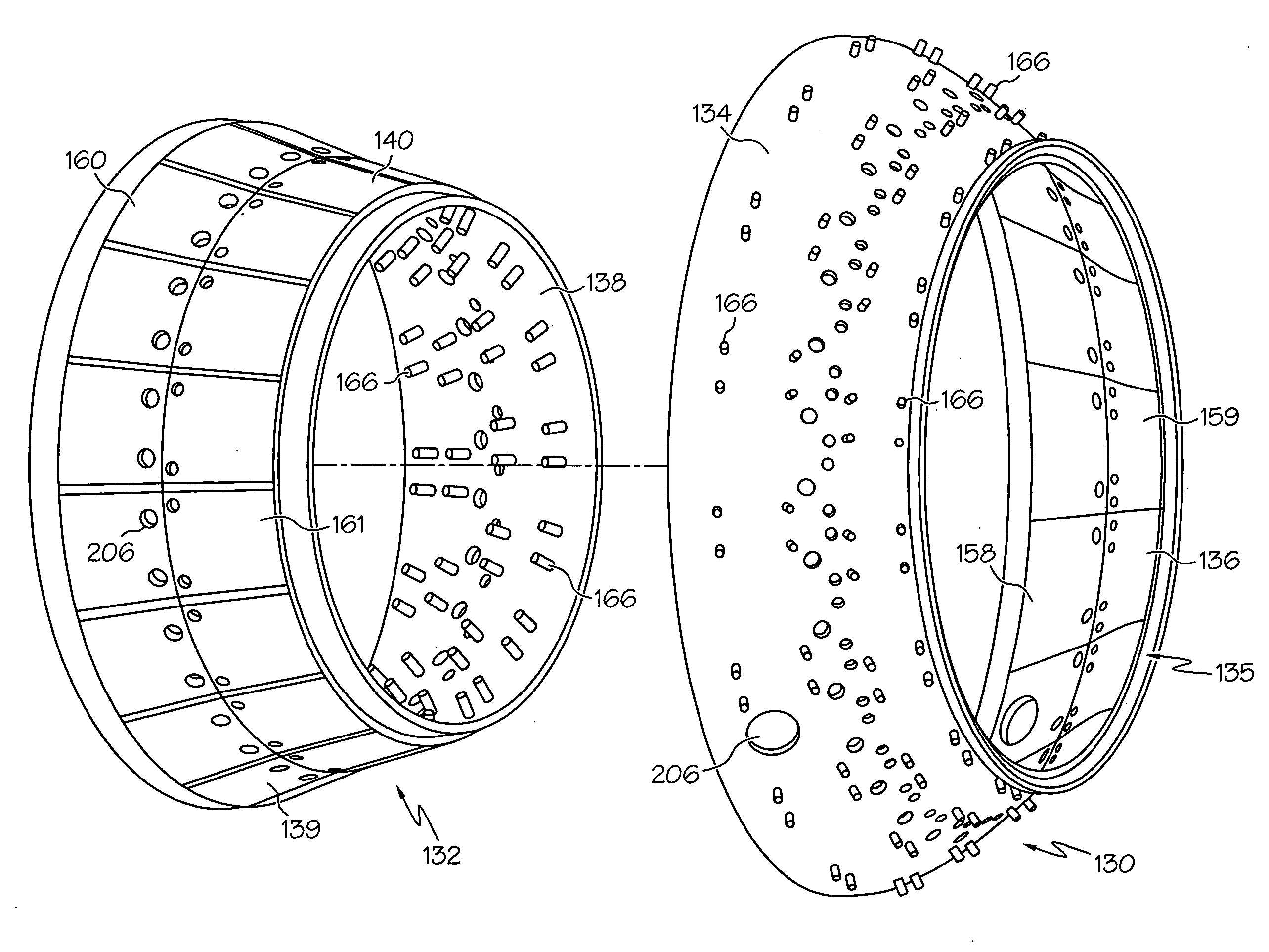
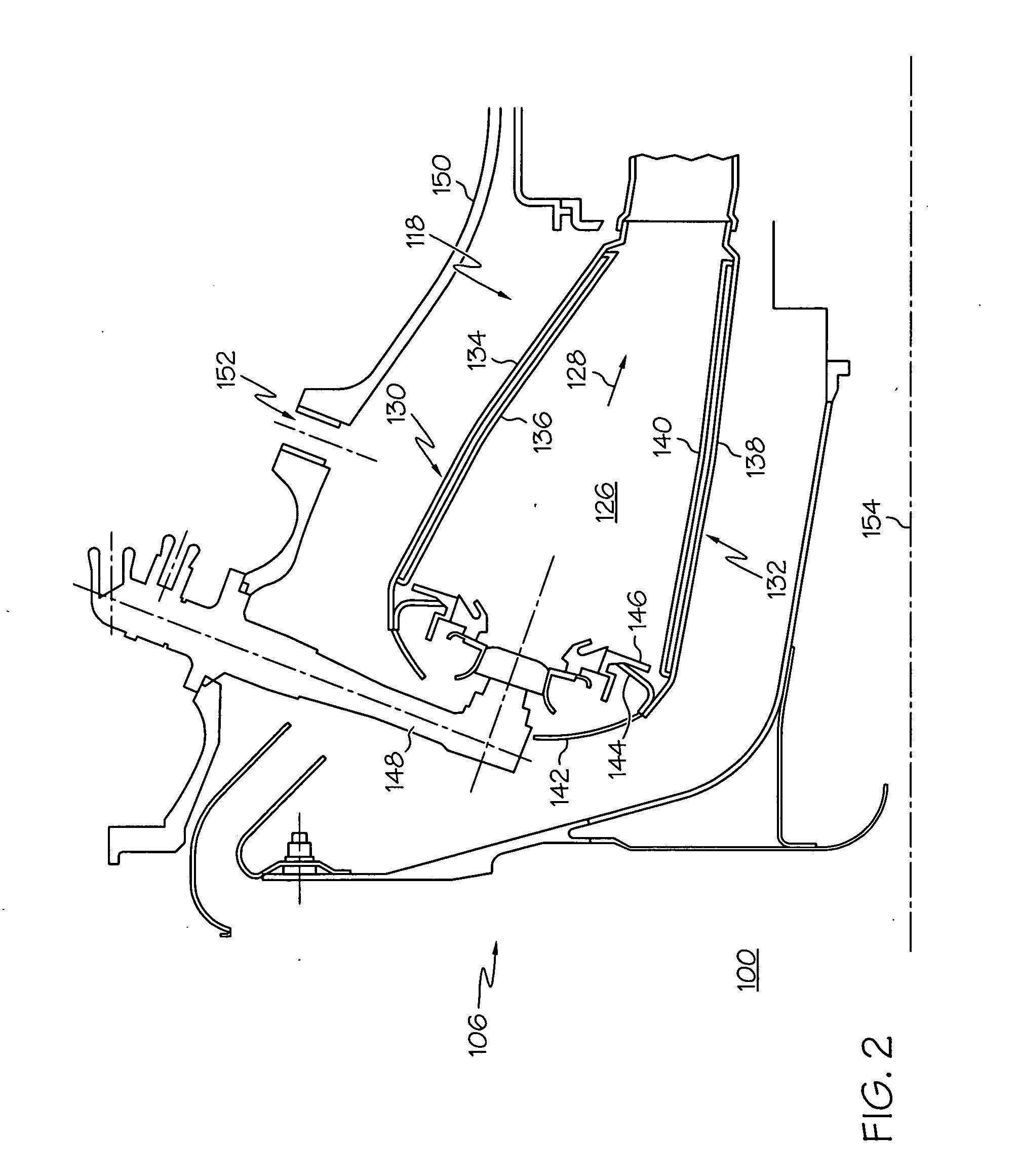
A dual wall structure for a combustor of a gas turbine engine including an inner liner and an outer liner coupled to a combustor dome and defining a combustion chamber there between. Each of the inner liner and the outer liner include an outer wall and an inner wall. Each of the outer walls includes a plurality of impingement holes formed therein for allowing a coolant to flow therethrough. Each of the inner walls is coupled to the outer wall via a plurality of threaded studs and includes a plurality of forward heat shield panels and a plurality of aft heat shield panels. Each of the plurality of forward heat shield panels and aft heat shield panels includes a plurality of side rails, a forward rail, and an aft rail including a plurality of controlled openings, that when coupled to the outer wall defines a single cavity there between. A plurality of cavities being formed by the plurality of forward and aft heat shield panels.

Description

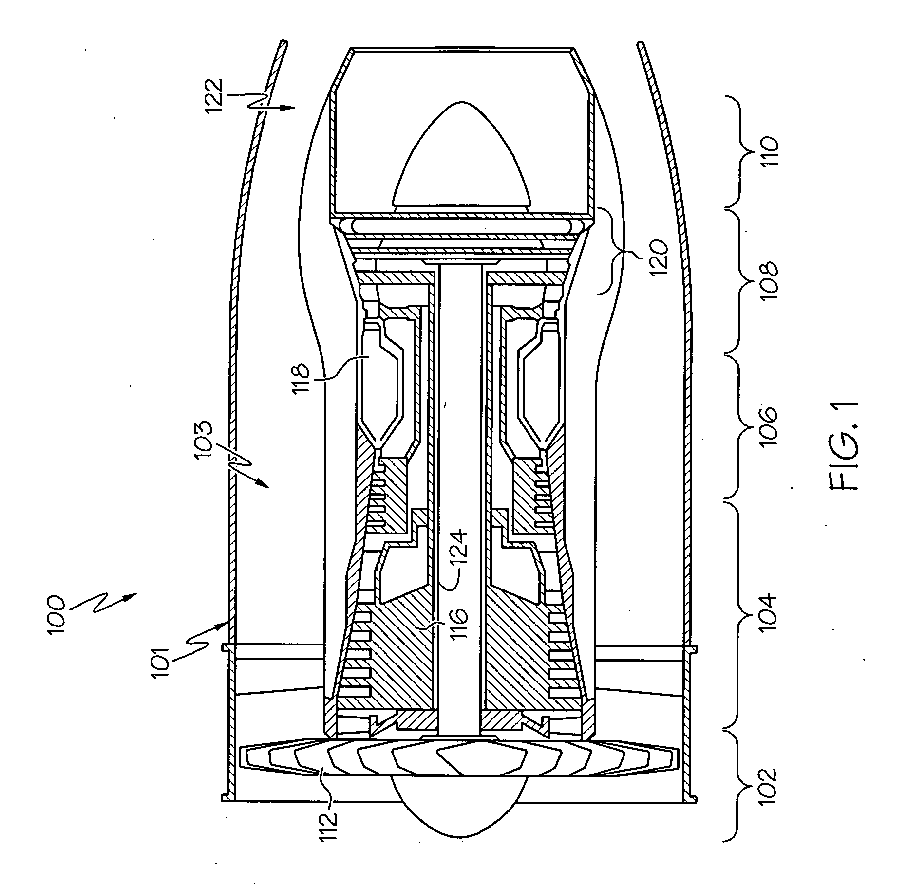
TECHNICAL FIELD[0001]The present invention relates to gas turbine engine combustors and, more particularly, to a wall structure for a gas turbine engine combustor.BACKGROUND[0002]A gas turbine engine may be used to power various types of vehicles and systems. A particular type of gas turbine engine that may be used to power aircraft is a turbofan gas turbine engine. A turbofan gas turbine engine may include, for example, five major sections, a fan section, a compressor section, a combustor section, a turbine section, and an exhaust section. The fan section is positioned at the front, or “inlet” section of the engine, and includes a fan that induces air from the surrounding environment into the engine, and accelerates a fraction of this air toward the compressor section. The remaining fraction of air induced into the fan section is accelerated into and through a bypass plenum, and out the exhaust section.[0003]The compressor section raises the pressure of the air it receives from the...

Claims


Application Information

Patent Timeline
Patent Type & Authority Applications(United States)
IPC IPC(8): F23R3/44F02C7/12
CPCF23R3/005F23R3/06Y02T50/675F23R2900/03042F23R2900/03044F23R2900/03041Y02T50/60
Inventor RUDRAPATNA, NAGARAJA S.WALDMAN, DAVID
Owner HONEYWELL INT INC
Why Eureka
Try Eureka