

Shock absorbing device and chair
a shock absorbing device and a chair technology, applied in the field of shock absorbing devices and chairs, can solve the problems of user's hand or the like being caught, the coil spring not buckling, and the inability to use in situations or environments in which buckling is desired, so as to prevent the coil spring from buckling, increase the safety, and prevent the effect of touching
- Summary
- Abstract
- Description
- Claims
- Application Information
AI Technical Summary
Benefits of technology
Problems solved by technology
Method used
Image

Examples
first exemplary embodiment
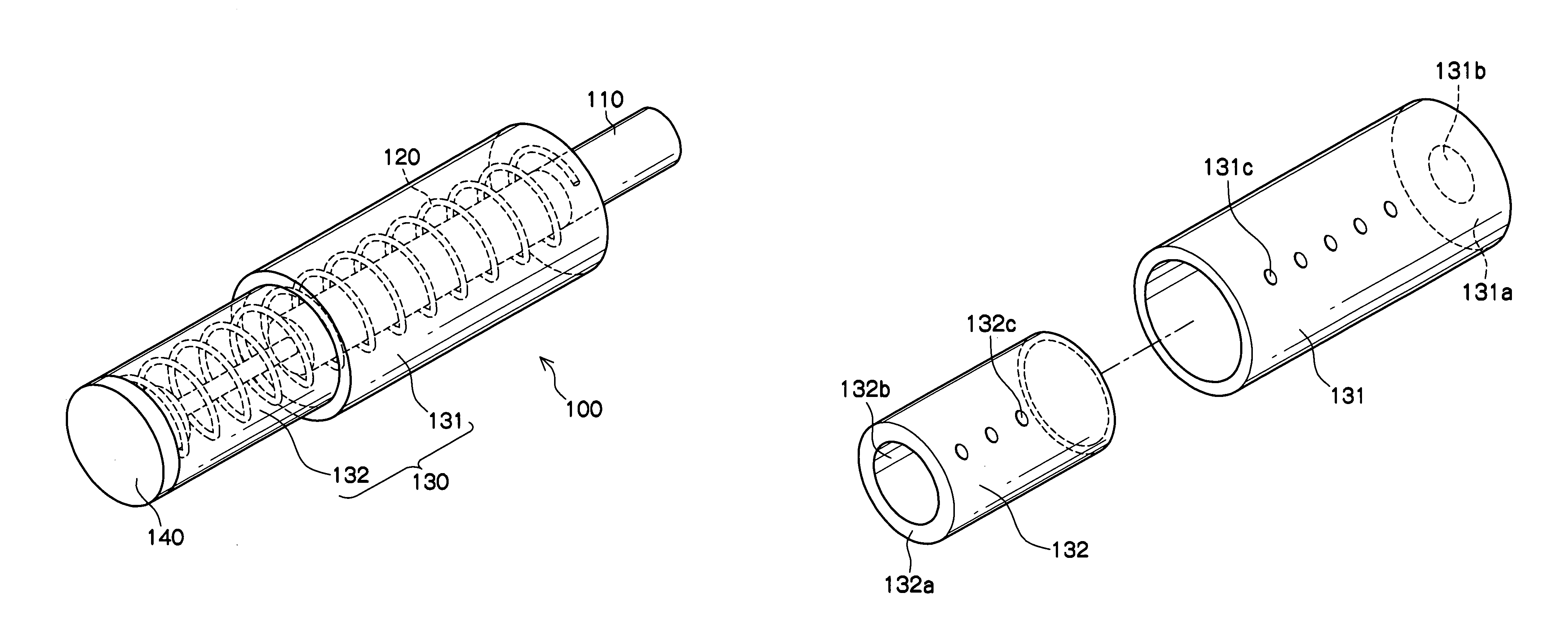
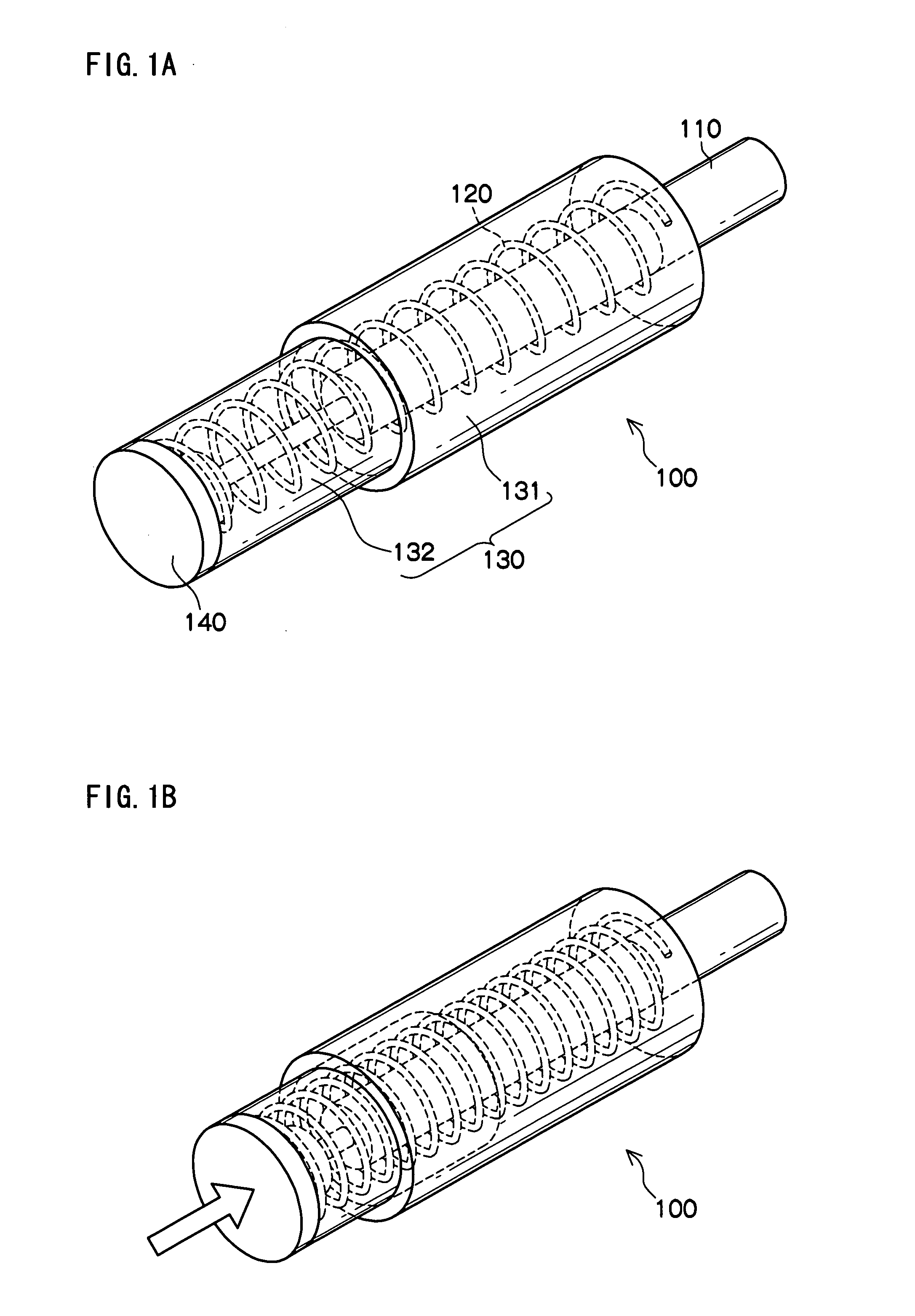
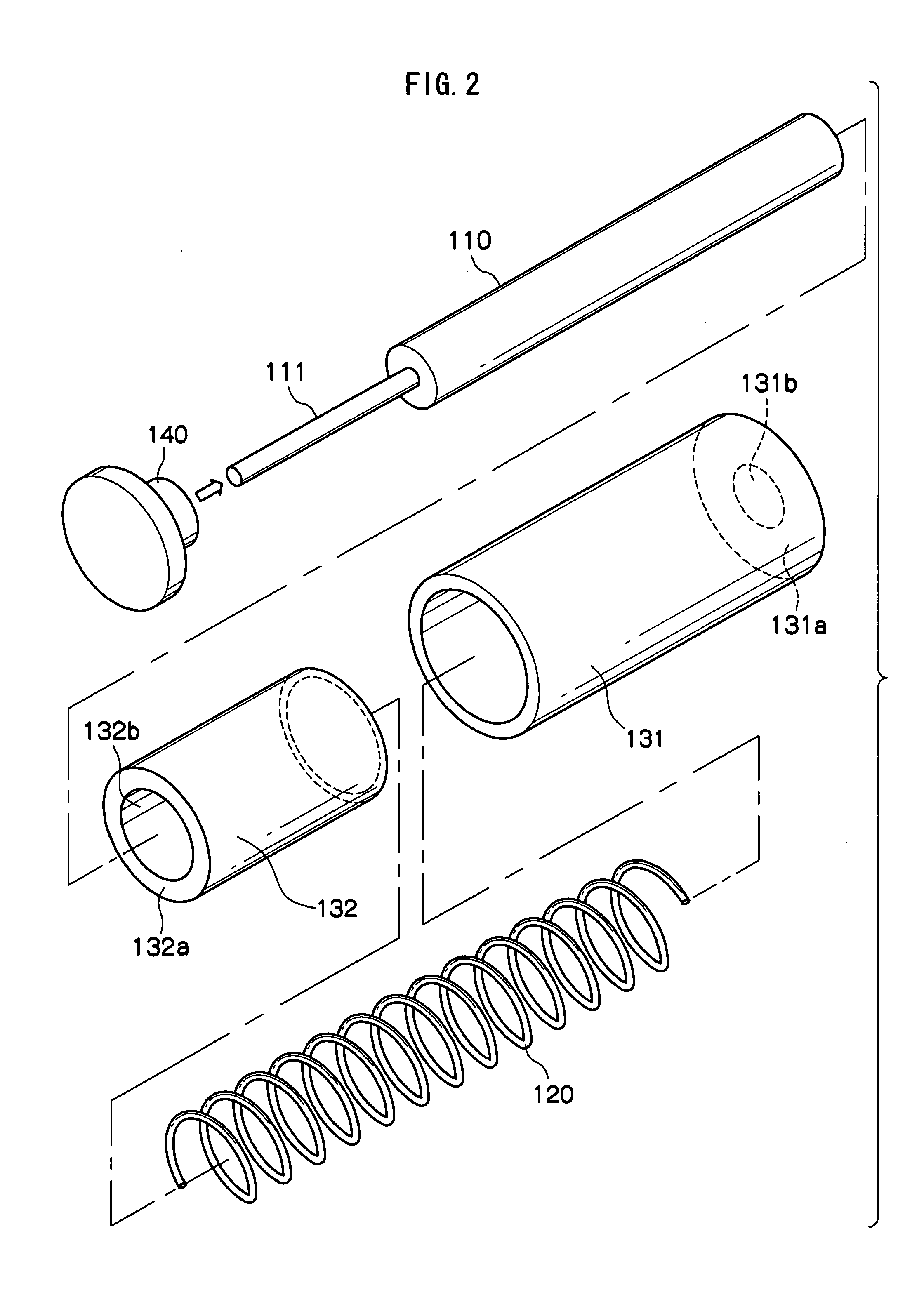
[0022]FIGS. 1A and 1B are transparent perspective views of the shock absorbing device 100 relating to the first exemplary embodiment. FIG. 1A is a perspective view before the shock absorbing device 100 is compressed. FIG. 1B is a perspective view when the shock absorbing device 100 is compressed. The shock absorbing device 100 includes a damper 110, a coil spring 120, a spring guide 130, and a lid member 140.
[0023]The damper 110 includes a cylinder having a cylindrical shape, and a piston rod that slides along the axial direction thereof. A viscous fluid such as oil is encapsulated inside the cylinder and applies a viscous resistance to the piston rod in order to resist a stroke.
[0024]The damper 110 may be configured by a shock absorber such as an oil damper.
[0025]The coil spring 120 is a compression coil spring that is disposed around the damper 110 so as to have an axis substantially in line with the axis of the damper 110.
[0026]The spring guide 130 is formed by a first spring gui...
second exemplary embodiment
[0059]FIGS. 3A and 3B are transparent perspective views of the shock absorbing device 100 relating to the second exemplary embodiment. FIG. 3A is a perspective view before the shock absorbing device 100 is compressed and FIG. 3B is an exploded perspective view of the damper 110 and the lid member 140.
[0060]In the second exemplary embodiment, the lid member 140 has a predetermined thickness along the axis of the damper 110. This thickness is larger than the thickness of the lid member 140 of the first exemplary embodiment. Other structures are the same as the first exemplary embodiment.
[0061]The lid member 140 of the first exemplary embodiment has a thickness that allows an insertion thereof into the insertion hole 132b. However, the lid member 140 of the second exemplary embodiment has a thickness that allows an insertion thereof into the coil spring 120 only to a predetermined depth when the coil spring 120 is accommodated inside the spring guide 130.
[0062]In other words, the lid m...
third exemplary embodiment
[0064]FIGS. 4A and 4B are transparent perspective views of the shock absorbing device 100 relating to the third exemplary embodiment. FIG. 4A is a perspective view before the shock absorbing device 100 is compressed, and FIG. 4B is an exploded perspective view of the damper 110 and the lid member 140.
[0065]The shock absorbing device 100 of the third exemplary embodiment further includes an elastic shock absorbing member 150 in addition to the structures explained in the first exemplary embodiment. The other structures are the same as in the first exemplary embodiment.
[0066]The elastic shock absorbing member 150 is formed, for example, by a cylindrical rubber and is placed inside (side at which it contacts with the coil spring 120) of the lid member 140.
[0067]The elastic shock absorbing member 150 prevents the lid member 140 and the damper 110 from directly coming in contact with each other and damaging each other when the coil spring 120 is compressed.
[0068]Further, when the lid mem...
PUM
 Abstract
Description
Claims
Application Information