
Integrated Modular Lighting Unit

a modular lighting and lightemitting device technology, applied in the field of lighting systems, can solve the problems of affecting the functionality of lighting and heating devices, affecting the operation of lighting equipment, and reducing the efficiency of optical devices by less than approximately 60%, and not providing a means for enabling colour control, intensity control, thermal control or any other control of lighting equipmen

Inactive Publication Date: 2010-04-22
KONINKLIJKE PHILIPS ELECTRONICS NV
View PDF53 Cites 141 Cited by
  • Summary
  • Abstract
  • Description
  • Claims
  • Application Information

AI Technical Summary

Benefits of technology

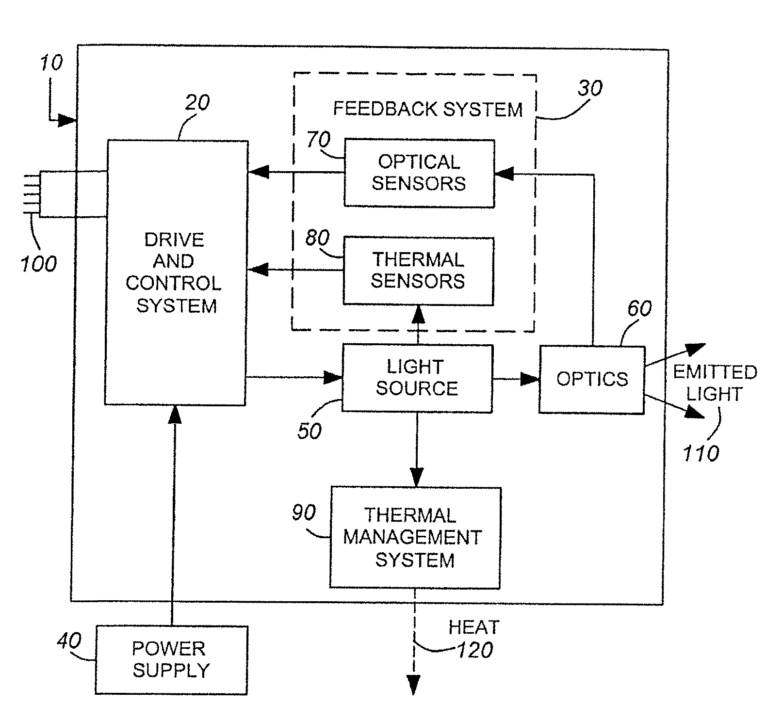
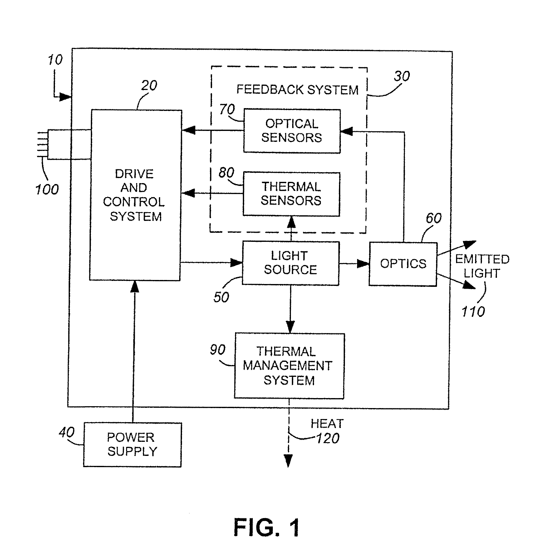
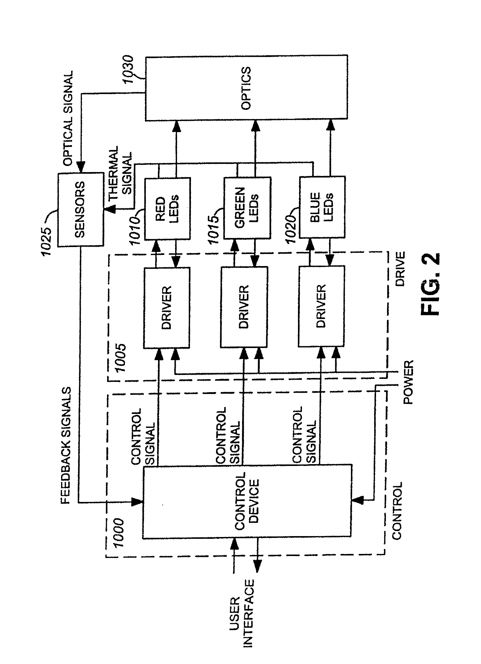
[0020]An object of the present invention is to provide an integrated modular lighting unit. In accordance with an aspect of the present invention, there is provided an integrated lighting module comprising: one or more light-emitting elements for generating illumination; an optical system optically coupled to the one or more light-emitting elements for manipulating the illumination; a feedback system for collecting information representative of operational characteristics of the one or more light-emitting elements, said feedback system generating one or more signals representative of said information; a thermal management system in thermal contact with the one or more light-emitting elements, said thermal management system for conducting heat away from the one or more light-emitting elements; a drive and control system receiving the one or more signals from the feedback system, said drive and control system regulating input power and generating and sending control signals to the one or more light-emitting elements, said control signals generated based on predetermined control parameters and said one or more signals.
[0021]In accordance with another aspect of the present invention, there is provide

Problems solved by technology

In particular these lamp forms can provide a protective mechanical surrounding that prevents either the escape of internal gases and / or the ingress of external gases that could contaminate the interior assembly of the lamp, thereby disrupting their functionality.
One of the key challenges for LEDs to achieve wide market adoption is the fact that they are significantly more variable in production and do not yet exhibit a standardized form or structure that is conducive to general illumination applications.
The optics associated with these packages are often compromised in order to provide a specific or desired beam pattern, resulting in optical efficiencies of less than approximately 60%.
This European patent discloses several features of a stand-alone lighting apparatus; however it does not provide a means for enabling colour control, intensity control, thermal control or any other control of the lighting apparatus beyond straight electrical drive of the LEDs.
Furthermore, this stand-alone lighting apparatus is not enabled to interact or communicate with other lighting apparatuses and therefore functions autonomously.
However, this apparatus does not include a proactive means for heat removal from the device or a means for heat regulation within this LED package.
Furthermore, while this package allows for connection to some type of external power supply, control or limiting of the power transmitted to the LEDs is not provided and therefore this apparatus may suffer from thermal and control limitations.
This system does not however include any means for heat management and there is no mention of any data collection during operation in order to control a variety of properties relating to the functionality of the light system and therefore this system may suffer from thermal and control limitations.
There is, however, no reference to heat regulation or operational feedback for the individual LED clusters and therefore this system may suffer from thermal and control limitations.
Furthermore, although this system is intended to form a complete system, there is no disclosure of any method or means for heat management and therefore this system may suffer from the heat regulation problems.
This system however does not include a means for dissipating heat from the LEDs or any optics for colour mixing, collimation or re-direction or any modularity of the lighting device.
This system may therefore suffer from thermal problems in addition to problems with the generation of substantially uniform illumination.
This system may therefore suffer from thermal regulation issues.
However, an integrated solution to satisfy general lighting requirements while exploiting the benefits of light-emitting devices is presently not available.

Method used


Image

  • Integrated Modular Lighting Unit
  • Integrated Modular Lighting Unit
  • Integrated Modular Lighting Unit

Examples


example 1

[0137]FIG. 8 illustrates a first example of the present invention integrated into a multi-lighting module quad flat pack (QFP) package. The lighting unit comprises a plurality of light-emitting elements 300 which also includes proximate optical elements. The reflector optic 310 manipulates the emissions from the light-emitting elements in a desired direction that may subsequently interact with a secondary optic 320, if this secondary optical is provided. In one embodiment this secondary optic can be a snap-on type optic thereby enabling ease of removal and inclusion of this optic. The light-emitting elements can be mounted on a CVD diamond substrate 370 through the use of a thermally conductive adhesive thereby enabling thermal conductivity there through. In direct thermal contact to the CVD diamond substrate is a heat pipe 360 which can be held in a desired position by a housing 350. The heat pipe(s) can enable transfer of heat generated by the light-emitting elements away therefro...

example 2

[0138]FIG. 9 illustrates a second example of the present invention formed as a modular lighting unit torchiere. The light-emitting elements 210 are mounted on a thermally conductive substrate 290 that is also thermally bonded to a heat pipe 220, thereby enabling heat transfer from the light-emitting elements to the heat pipe for subsequent dissipation. The ends of the heat pipe are in contact with the housing 250 which may comprise slits 280 therein enabling the flow of air within the housing thereby providing an additional means for heat dissipation. Positioned below and in operative contact with the light-emitting elements in a PC board 240 including a drive and control system mounted thereon, wherein this PC board can be operatively connected to a power supply 260, for example. Furthermore the emissions from the light-emitting elements can be manipulated by an optical diffuser 230.

example 3

[0139]FIG. 10 illustrates a third example of the present invention formed as a modular lighting unit luminaire wherein the light-emitting elements 420 are mounted on a substrate or a heat pipe 410 or optionally the light-emitting elements can be directly mounted to the sidewall of the heat pipe. Positioned below the heat pipe and operatively connected to the light-emitting elements is a control board 430. A diffuser / reflector 400 is provided to enable manipulation of the emissions of the light-emitting elements.


PUM


Abstract

The present invention provides an integrated self-contained lighting module which can be used on its own, or in conjunction with other modules to produce white light, or light of any other colour within the colour spectrum. Each module comprises one or more light-emitting elements, a drive and control system, a feedback system, thermal management system, optical system, and optionally a communication system enabling communication between modules and / or other control systems. Depending on the configuration, the lighting module can operate autonomously or its functionality can be determined based on either or both internal signals and externally received signals.

Description

RELATED APPLICATIONS[0001]This patent application claims priority under 35 U.S.C. §120 to U.S. Non-Provisional patent application Ser. No. 10 / 568,996, entitled “Integrated Modular Lighting Unit,” filed Nov. 29, 2005, which is a United States national phase filing under 35 U.S.C. §371 of International Application No. PCT / CA2005 / 001792, filed Nov. 29, 2005, which claims priority under 35 U.S.C. §119 to U.S. Provisional Patent Application No. 60 / 631,466, filed Nov. 29, 2004, and to U.S. Provisional Patent Application No. 60 / 668,786, filed Apr. 5, 2005. The complete disclosure of all the foregoing priority and related applications is hereby fully incorporated herein by reference.FIELD OF THE INVENTION[0002]The present invention pertains to the field of lighting systems and in particular to an integrated modular light-emitting device lighting unit wherein the modular lighting unit is capable of dimming and control of light colour and correlated colour temperature.BACKGROUND[0003]Having r...

Claims


Application Information

Patent Timeline
IPC IPC(8): H01J13/32
CPCF21K9/00F21V29/004F21V29/2212F21Y2101/02H05B33/0803F21V29/74H05B33/0869F21V29/006F21S6/00F21V29/717H05B33/0821F21Y2115/10F21V29/51H05B45/22H05B45/28H05B45/24H05B47/175H05B45/00H05B45/40H05B45/325H05B45/36H05B45/3725H05B45/375H05B45/38H05B45/385H05B45/395
Inventor ASHDOWN, IANJUNGWIRTH, PAULROBINSON, SHANE P.SCHICK, PHILIPPESPEIER, INGOYORK, ALLAN BRENT
Owner KONINKLIJKE PHILIPS ELECTRONICS NV
Learn More