

Multi-mode HVAC system with thermoelectric device
a thermoelectric device and multi-mode technology, applied in ventilation systems, heating types, domestic cooling apparatuses, etc., can solve problems such as various drawbacks in existing automotive thermoelectric device hvac architectures
- Summary
- Abstract
- Description
- Claims
- Application Information
AI Technical Summary
Benefits of technology
Problems solved by technology
Method used
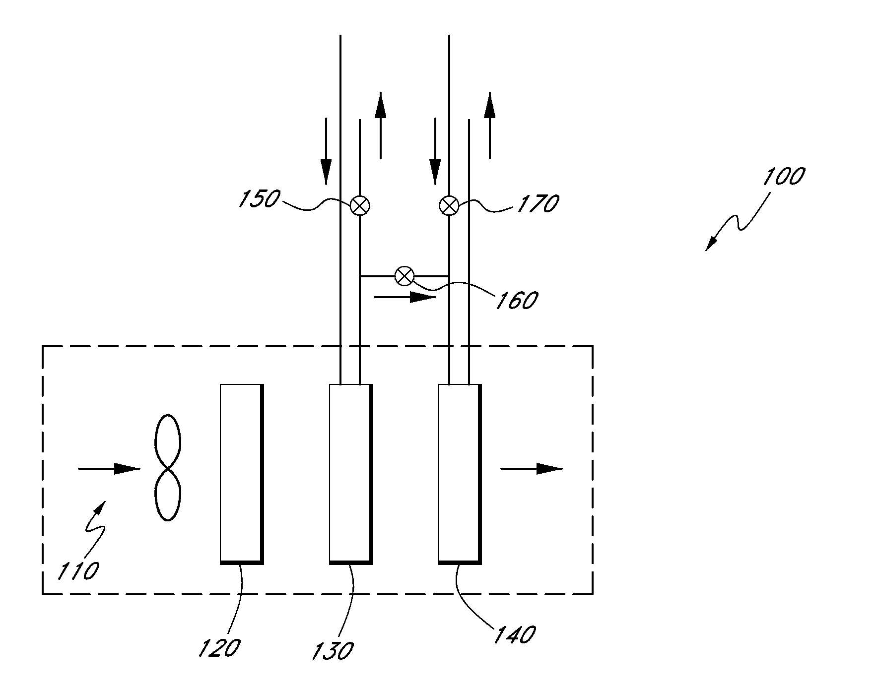
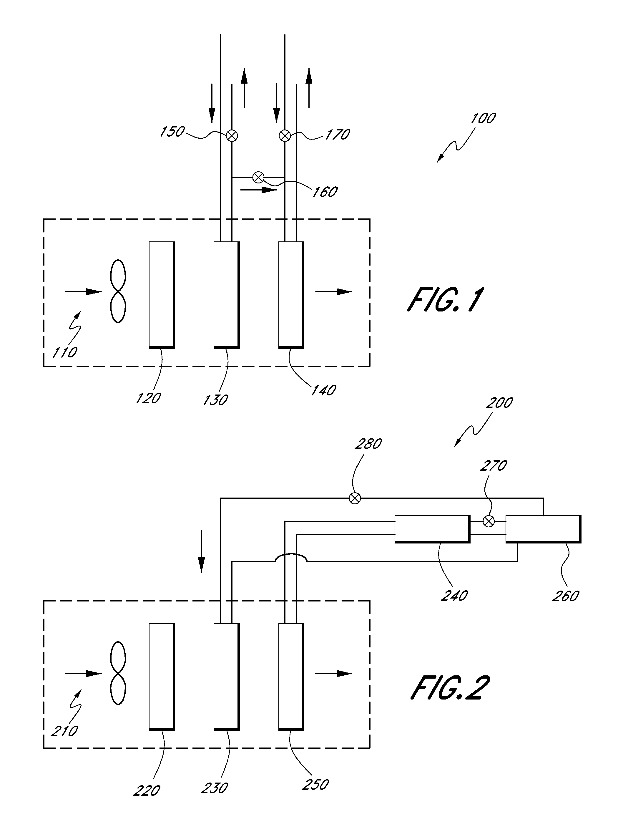
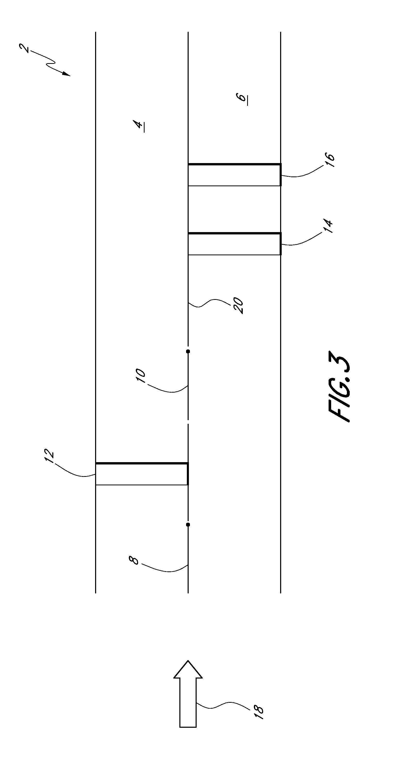
Image

Examples
Embodiment Construction
[0045]Although certain preferred embodiments and examples are disclosed herein, inventive subject matter extends beyond the specifically disclosed embodiments to other alternative embodiments and / or uses of the inventions, and to modifications and equivalents thereof. Thus, the scope of the inventions herein disclosed is not limited by any of the particular embodiments described below. For example, in any method or process disclosed herein, the acts or operations of the method or process may be performed in any suitable sequence and are not necessarily limited to any particular disclosed sequence.
[0046]For purposes of contrasting various embodiments with the prior art, certain aspects and advantages of these embodiments are described. Not necessarily all such aspects or advantages are achieved by any particular embodiment. Thus, for example, various embodiments may be carried out in a manner that achieves or optimizes one advantage or group of advantages as taught herein without nec...
PUM
| Property | Measurement | Unit |
|---|---|---|
| Temperature | aaaaa | aaaaa |
| Flow rate | aaaaa | aaaaa |
| Polarity | aaaaa | aaaaa |
Abstract
Description
Claims
Application Information