Device for the combined locking and rotation angle limitation of a camshaft adjuster

Inactive Publication Date: 2010-04-29
SCHAEFFLER TECH AG & CO KG
View PDF9 Cites 7 Cited by
  • Summary
  • Abstract
  • Description
  • Claims
  • Application Information

AI Technical Summary

Benefits of technology

[0018]In contrast, it is the object of the present invention to provide a locking device of a camshaft adjuster for an internal combustion engine, by means of which locking device the abo

Problems solved by technology

A disadvantage of conventional camshaft adjusters is the fact that the assembly thereof is relatively expensive and time-consuming since, for an alignment of the locking device, it is necessary to take into consideration that rotational position of the rotor which corresponds to the desired base position, which rotational position itself is already afflicted with t

Method used


Image

  • Device for the combined locking and rotation angle limitation of a camshaft adjuster
  • Device for the combined locking and rotation angle limitation of a camshaft adjuster
  • Device for the combined locking and rotation angle limitation of a camshaft adjuster

Examples


Example

DETAILED DESCRIPTION OF THE DRAWINGS

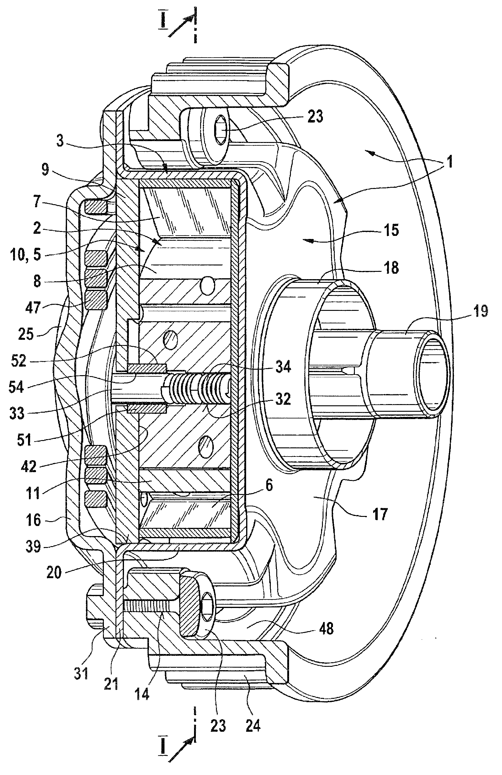
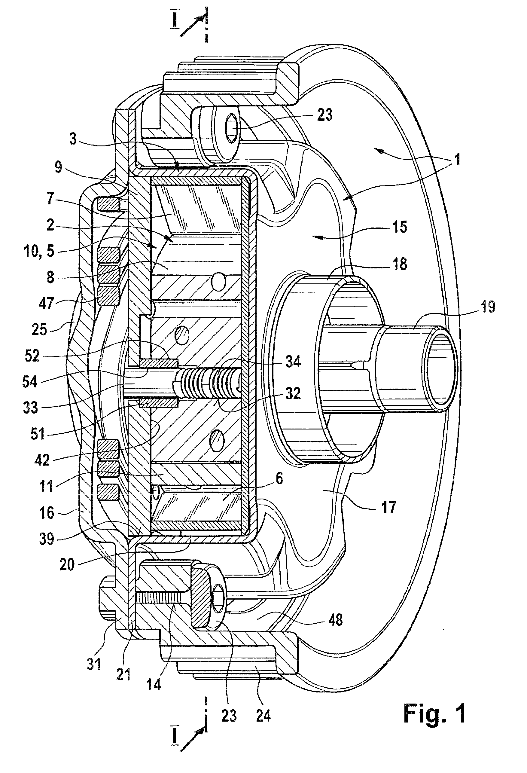
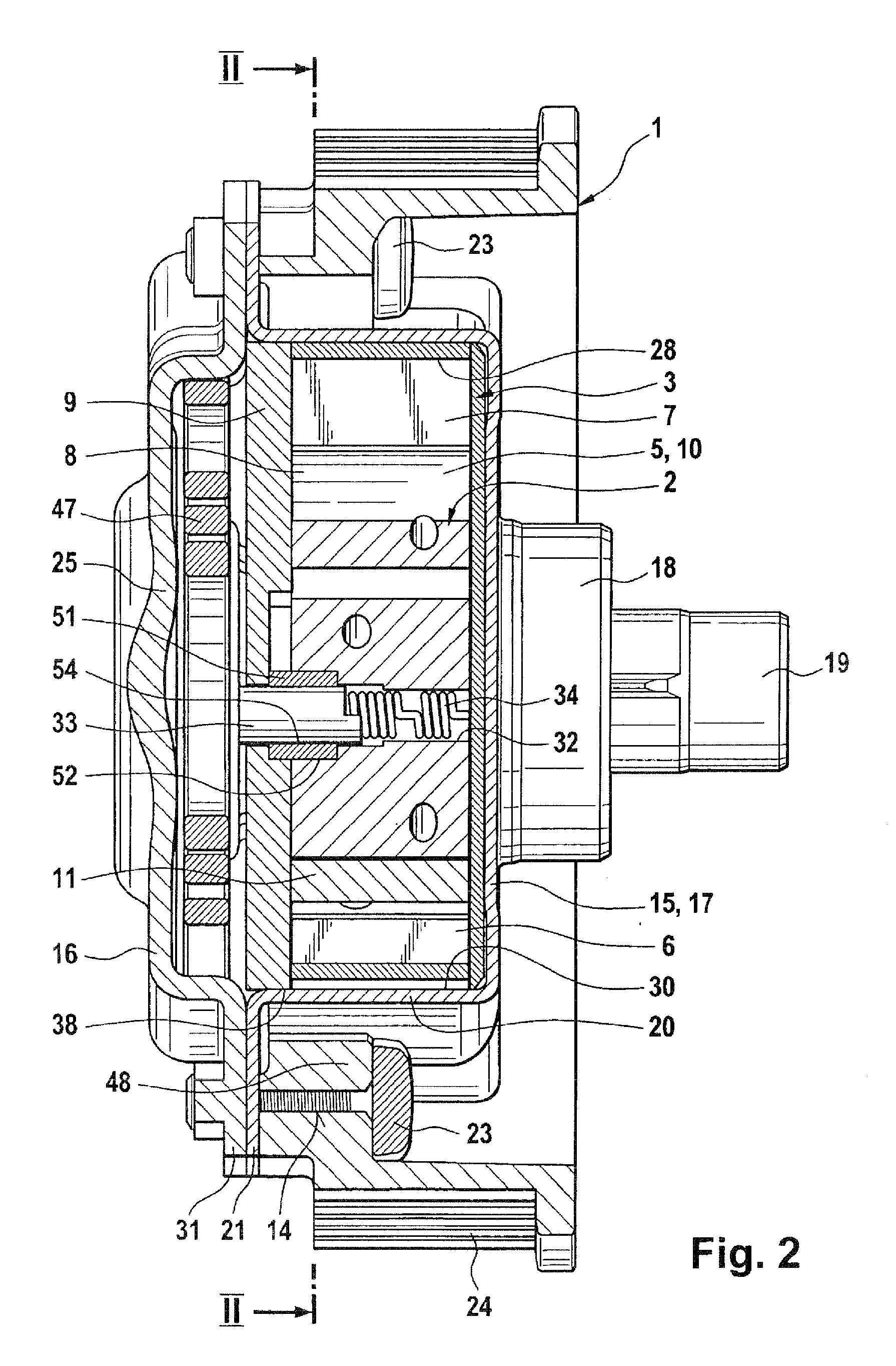
[0042]The Figures illustrate a combined locking and rotational angle limiting device of a vane-type camshaft adjuster for the variable adjustment of the control times of the gas exchange valves of an internal combustion engine.

[0043]The vane-type camshaft adjuster comprises, as a drive input part, an outer rotor 1, which is drive-connected to a crankshaft by means of a drive input wheel 24, and as a drive output part, an inner rotor 2, referred to below as a rotor, which is arranged concentrically within the outer rotor 1 and which is rotationally fixedly connected to a camshaft 19.

[0044]The outer rotor 1 is itself constructed from a plurality of components which are rotationally fixedly connected to one another. The outer rotor 1 thus comprises a stator 3 which is formed, for example, as a sheet-metal part and whose inner lateral surface 4 is provided with a plurality of radial recesses 5 which are delimited in each case by radial side walls 6, 7...


PUM


Abstract

A locking and rotation angle device for locking and setting maximum rotational adjustability of a drive part fixed to the crankshaft and a driven part fixed to the camshaft of a camshaft adjuster. The driven part is pivotably adjusted to the drive part, which has a locking bar received in the drive or driven part, a locking bar member formed in the respectively other part, and a rotation angle limiting member formed in the correspondingly other part. Limiting wall sections serve as stops for the locking bar for adjusting a maximum rotational adjustability. The locking bar member, rotation angle limiting member, and locking bar are disposed such that the locking bar is displaced via the displacement mechanism into a locking position, engaging into the locking bar member, and into an unlocking position, in which it is released by the locking bar member and engages in the rotation angle limiting member.

Description

FIELD OF THE INVENTION[0001]The invention lies in the technical field of internal combustion engines and relates to a combined locking and rotational angle limiting device of a camshaft adjuster for an internal combustion engine.PRIOR ART[0002]In internal combustion engines, gas exchange valves are actuated by the cams of a camshaft which is set in rotation by the crankshaft. For this purpose, the cams conventionally roll on cam followers such as rocker arms, oscillating levers or cup tappets which act counter to the spring force of a valve spring which holds the gas exchange valve in a closed position. The control times of the gas exchange valves can be defined in a targeted fashion by means of the arrangement and shape of the cams.[0003]Against the background of thermodynamic processes, it has proven to be advantageous when, during the operation of the internal combustion engine, the control times of the gas exchange valves are manipulated as a function of the present operating st...

Claims


Application Information

Patent Timeline
IPC IPC(8): F01L1/34
CPCF01L1/3442F01L2001/34453F01L2001/34483F01L2001/34469F01L2001/34459
Inventor HERTRICH, STEFFEN
Owner SCHAEFFLER TECH AG & CO KG
Why Eureka
Try Eureka