Semiconductor electronic component and semiconductor device using the same

a technology of semiconductor electronic components and semiconductor devices, which is applied in the direction of polyether adhesives, adhesive types, transportation and packaging, etc., can solve the problems of inability to perform wire bonding, inability to achieve high-density packages and inability to achieve further improvement of density of semiconductor integrated circuits in chip-on-chip type sips. the effect of increasing the integration density of semiconductor chips, which can be included in one package, and reducing the total thickness of the whol

Inactive Publication Date: 2010-04-29
SUMITOMO BAKELITE CO LTD
View PDF5 Cites 29 Cited by
  • Summary
  • Abstract
  • Description
  • Claims
  • Application Information

AI Technical Summary

Benefits of technology

[0008]The present inventors diligently made researches in consideration of the above-described problems of the conventional techniques, and successfully performed electrical connection and filling between semiconductor chips together by minimizing bleeding of a resin component at the time of meltdown of an adhesion film. Thus, a chip-on-chip type semiconductor electronic component and a semiconductor device which can meet the requirements for further density increase were successfully obtained.
[0019]The present invention can provide a semiconductor electronic component in which the distance between semiconductor chips is 50 μm or less, and preferably 25 μm or less. By using the semiconductor electronic component of the present invention, the total thickness of the whole component to be packaged in a semiconductor device can be reduced, and the weight of the whole component to be packaged can also be reduced.
[0020]The present invention can also provide a semiconductor electronic component in which the shortest distance between the side surface of the upper semiconductor chip and an external electrode provided on the lower semiconductor chip is 1 mm or less. By using the semiconductor electronic component of the present invention, the integration density of semiconductor chips, which one package can include, can be increased. Further, the whole component to be packaged can be miniaturized.
[0021]Moreover, according to a preferred embodiment of the present invention, the present invention can provide a semiconductor electronic component in which the shortest distance between internal electrodes provided on the surface of a semiconductor chip is 50 μm or less. By using the semiconductor electronic component of the present invention, the amount of information, which one package can include, can be increased.
[0022]According to a preferred embodiment of the present invention, the present invention can provide a multiple-layer stack type semiconductor electronic component in which a plurality of semiconductor chips are stacked. According to a preferred embodiment of the present invention, in the multiple-layer stack type semiconductor electronic component of the present invention, the distance between semiconductor chips is 50 μm or less, and preferably 25 μm or less, and the shortest distance between the side surface of the upper semiconductor chip and an external electrode provided on the lower semiconductor chip is 1 mm or less. Further, according to a preferred embodiment of the present invention, in the multiple-layer stack type semiconductor electronic component of the present invention, the shortest distance between internal electrodes provided on the surface of a semiconductor chip is 50 μm or less. By using the above-described semiconductor electronic component of the present invention, the integration density of semiconductor chips, which one package can include, can be further increased.
[0023]Furthermore, the present invention can provide a semiconductor device in which the semiconductor electronic component of the present invention is mounted on a substrate. The semiconductor device of the present invention meets requirements for sophistication and miniaturization of electronic devices since it allows increase of the integration density of semiconductor chips which one package can include.

Problems solved by technology

However, in this step of underfill filling, the filling resin injected between the semiconductor chips bleeds and an external electrode provided on the surface of the lower semiconductor chip is contaminated thereby, and for this reason, there is a problem that it is impossible to perform wire bonding.
These requirements interrupt high-density package of semiconductor integrated circuits.
However, none of these methods realized further improvement of density increase of semiconductor integrated circuits in chip-on-chip type SiPs.

Method used


Image

  • Semiconductor electronic component and semiconductor device using the same
  • Semiconductor electronic component and semiconductor device using the same
  • Semiconductor electronic component and semiconductor device using the same

Examples


first embodiment

(1) First Embodiment

[0076]Firstly, a method of producing a semiconductor electronic component according to the first embodiment of the present invention will be described with reference to FIG. 3.

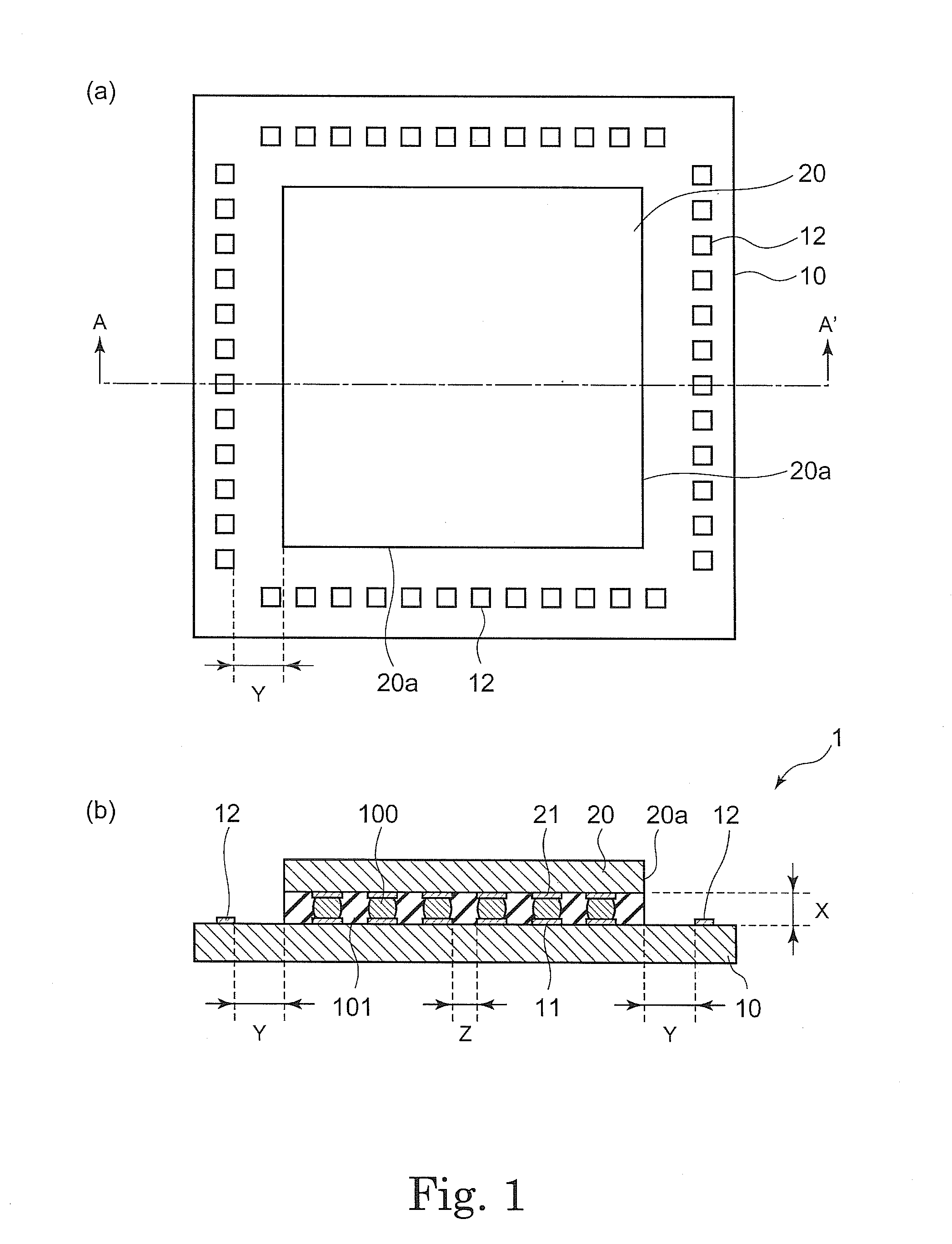
[0077]As shown in FIG. 3(a), firstly, a semiconductor chip 10 in which an internal electrode 11 is provided on a circuit surface thereof and a semiconductor chip 20 in which an internal electrode 21 is provided on a circuit surface thereof are prepared. In order to obtain good electrical connection, surfaces of the internal electrodes 11 and 21 may be subjected to treatment such as washing, polishing, plating and surface activation in advance. For example, as shown in FIG. 3(a), UBM (Under Barrier Metal) layers 103 and 104 may be formed on the surfaces of the internal electrodes 11 and 21 using Ti, Ti / Cu, Cu, Ni, Cr / Ni or the like. One or more UBM layers may be formed. The surfaces of the semiconductor chips 10 and 20 may be subjected to surface stabilization treatment in advance for the pu...

second embodiment

(2) Second Embodiment

[0149]Next, a method of producing a semiconductor electronic component according to the second embodiment of the present invention will be described with reference to FIG. 4.

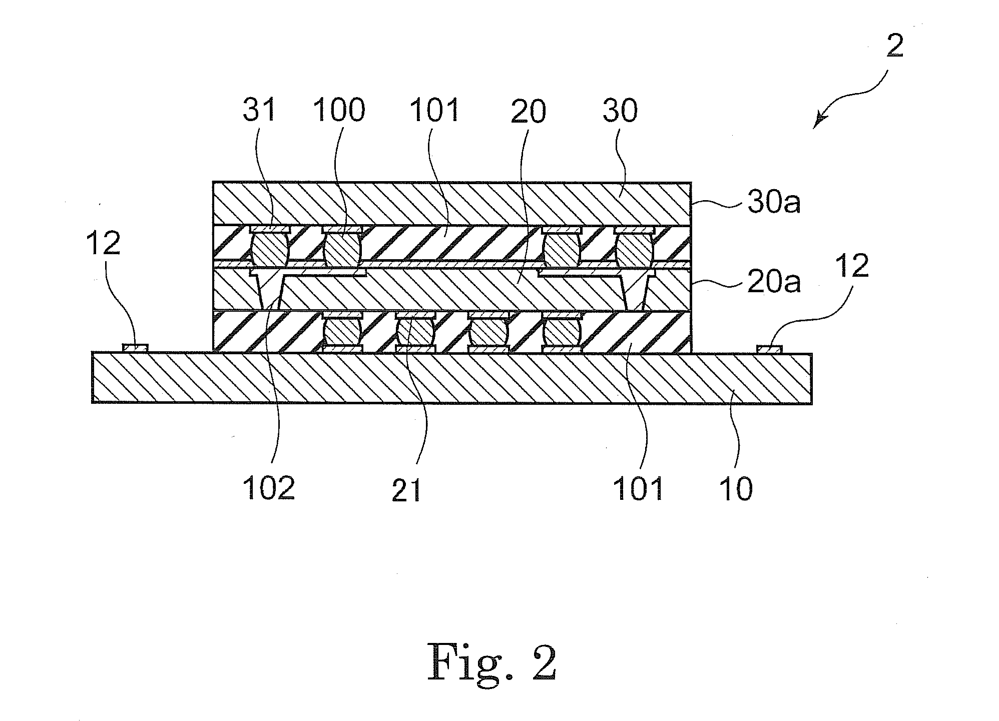
[0150]As shown in FIG. 4(a), a semiconductor chip 10 on which an internal electrode 11 is provided and a semiconductor chip 20 on which an internal electrode 21 is provided are positioned so that the surfaces thereof on which the internal electrode is provided (circuit surfaces) are opposed to each other.

[0151]On the surface of the semiconductor chip 10 and the surface of the semiconductor chip 20, a protecting layer 107 may be formed in a way in which positions at the internal electrodes 11 and 21 are opened. For example, a protecting layer made of organic resin such as a polyimide film, a polybenzooxazol film and a benzocyclobutene film may by formed. This allows the solder component to be more easily introduced into the space between the internal electrodes opposed to each other, and good...

examples

[0172]Hereinafter, the present invention will be specifically described by way of illustrative examples. However, the present invention is not limited thereto.

[0173]Thermosetting adhesive films A to Y were prepared as described below.

(1) Preparation of Thermosetting Adhesive Film A

[0174]Components described in Table 1 were mixed with acetone employing the formulation A in Table 1 in a manner in which the solid content was 40 wt %. Varnish thus obtained was applied on a polyester sheet subjected to antistatic treatment using a comma knife-type coater. It was dried for 3 minutes at 70° C., which is the temperature at which the above-described acetone volatilizes, and thereby a thermosetting adhesive film A having the thickness of 25 μm was prepared.

(2) Preparation of Thermosetting Adhesive Film B

[0175]Components described in Table 1 were mixed with NMP (N-methyl-2-pyrrolidone) employing the formulation B in Table 1 in a manner in which the solid content was 40 wt %. Varnish thus obtai...


PUM

PropertyMeasurementUnit
distanceaaaaaaaaaa
distanceaaaaaaaaaa
distanceaaaaaaaaaa

Abstract

The problem of the present invention is to provide a chip-on-chip type semiconductor electronic component and a semiconductor device which can meet the requirements for further density increase of semiconductor integrated circuits.The present invention provides: a chip-on-chip type semiconductor electronic component in which a circuit surface of a first semiconductor chip and a circuit surface of a second semiconductor chip are opposed to each other, wherein the distance X between the first semiconductor chip and the second semiconductor chip is 50 μm or less, and the shortest distance Y between the side surface of the second semiconductor chip and the first external electrode is 1 mm or less; and a semiconductor device comprising the same.

Description

TECHNICAL FIELD[0001]The present invention relates to a chip-on-chip type semiconductor electronic component and a semiconductor device comprising the same. More specifically, the present invention relates to a semiconductor electronic component which can meet the requirements for density increase of semiconductor integrated circuits and a semiconductor device comprising the same.BACKGROUND ART[0002]Recently, as the need for sophistication and miniaturization of electronic devices has been increased, the technique for high-density package of semiconductor integrated circuits has been developed. One example of such packaging techniques is a chip-on-chip type System in Package (SiP) in which a semiconductor chip is mounted on another semiconductor chip face down. Attention is focused on this structure because it allows thickness reduction of packages and is excellent in reliability of electrical connection.[0003]In general, in a chip-on-chip type SiP, connection between semiconductor ...

Claims


Application Information

Patent Timeline
Patent Type & Authority Applications(United States)
IPC IPC(8): H01L23/498H01L23/538H01L23/28
CPCC08G59/42C08G59/621C08L33/08C08L63/00C09J163/00C09J179/08H01L23/3128H01L24/05H01L24/11H01L24/12H01L24/16H01L24/81H01L24/83H01L24/90H01L25/0657H01L2224/0401H01L2224/04042H01L2224/13022H01L2224/13099H01L2224/16145H01L2224/16225H01L2224/32145H01L2224/48091H01L2224/48227H01L2224/48465H01L2224/73204H01L2224/81101H01L2224/81801H01L2224/83101H01L2224/838H01L2224/83907H01L2225/0651H01L2225/06513H01L2225/06517H01L2225/06541H01L2924/01002H01L2924/01005H01L2924/01007H01L2924/01009H01L2924/01013H01L2924/01014H01L2924/01015H01L2924/01022H01L2924/01027H01L2924/01028H01L2924/01029H01L2924/0103H01L2924/01033H01L2924/01047H01L2924/01049H01L2924/0105H01L2924/01059H01L2924/01074H01L2924/01075H01L2924/01078H01L2924/01082H01L2924/01327H01L2924/014H01L2924/14H01L2924/15311H01L2224/32225H01L2924/0132H01L24/32H01L24/48H01L2224/2919H01L2924/01006H01L2924/01019H01L2924/01023H01L2924/01024H01L2924/01045H01L2924/01072H01L2924/0665H01L2924/0133H01L2224/29109H01L2224/29111H01L2224/05001H01L2224/0554H01L2224/2929H01L2224/293H01L2224/83851H01L2224/131H01L2224/13109H01L2224/13111H01L2224/83886H01L2224/16235Y10T428/256C08L2666/22C08L2666/02H01L2924/00014H01L2924/00H01L2924/00012H01L2924/01083H01L2224/05554H01L2224/1146H01L2224/81815H01L2924/12042H01L2924/181H01L2224/45099H01L2224/45015H01L2924/207C09J133/00C09J171/10H01L23/12
Inventor KATSURAYAMA, SATORUYAMASHIRO, TOMOEHIRANO, TAKASHI
Owner SUMITOMO BAKELITE CO LTD
Why Eureka
Try Eureka