
System and method to remotely interact with NANO devices in an oil well and/or water reservoir using electromagnetic transmission

a technology of electromagnetic transmission and nano devices, applied in the field of subsurface fluid recovery systems, can solve the problem and achieve the effect of reducing the flow of oil to the well

Inactive Publication Date: 2010-04-29
LOCKHEED MARTIN CORP
View PDF9 Cites 61 Cited by
  • Summary
  • Abstract
  • Description
  • Claims
  • Application Information

AI Technical Summary

Benefits of technology

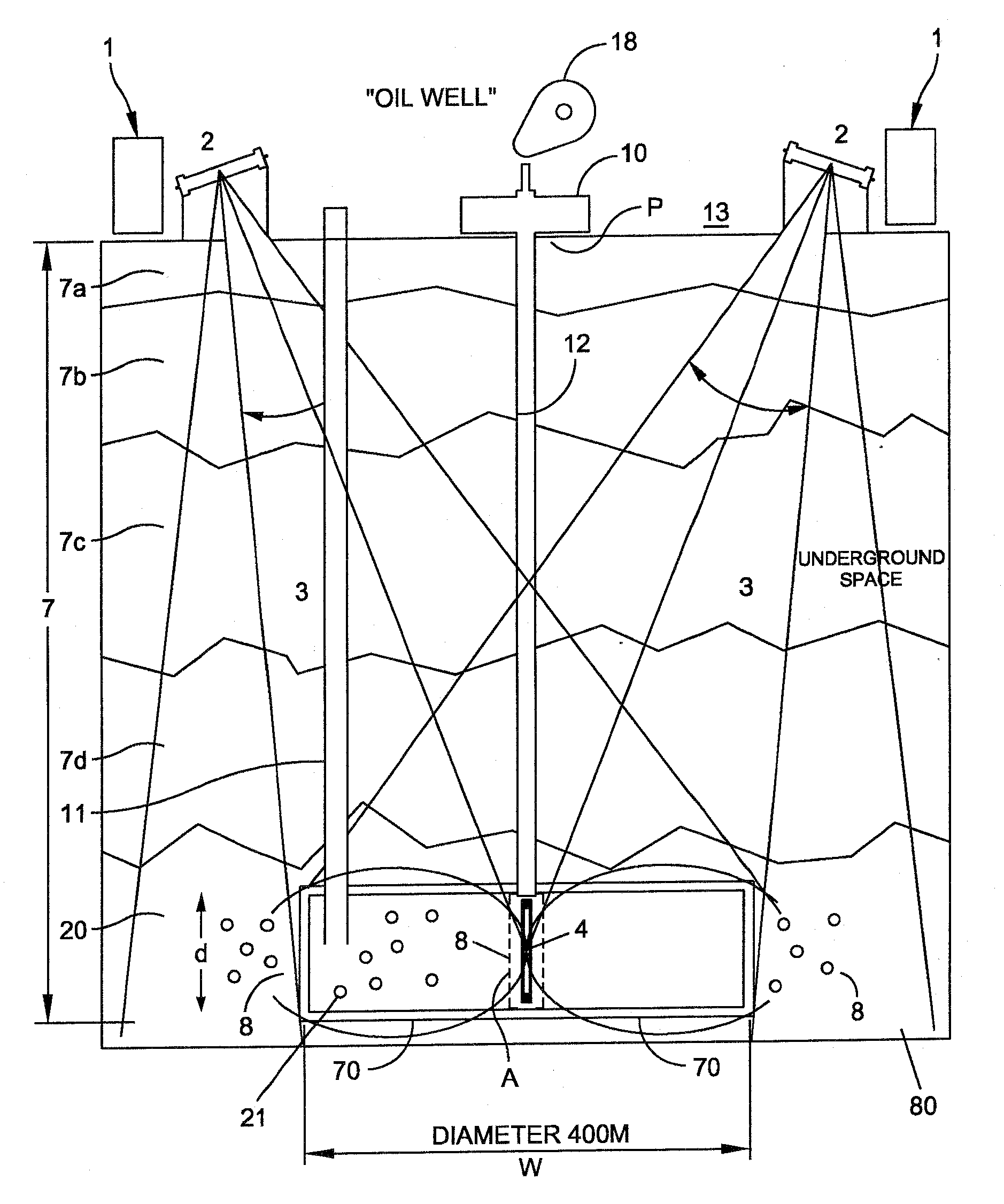
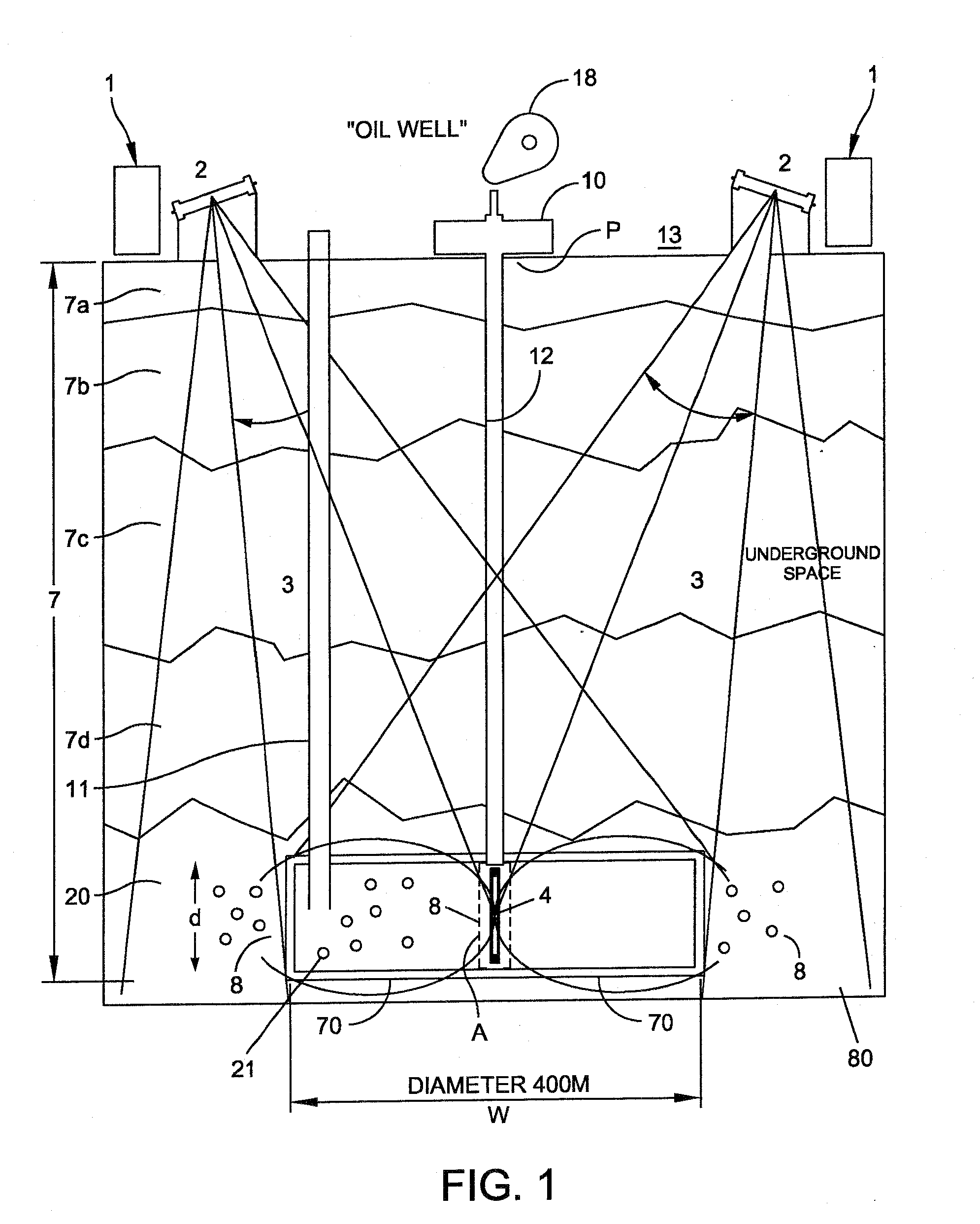
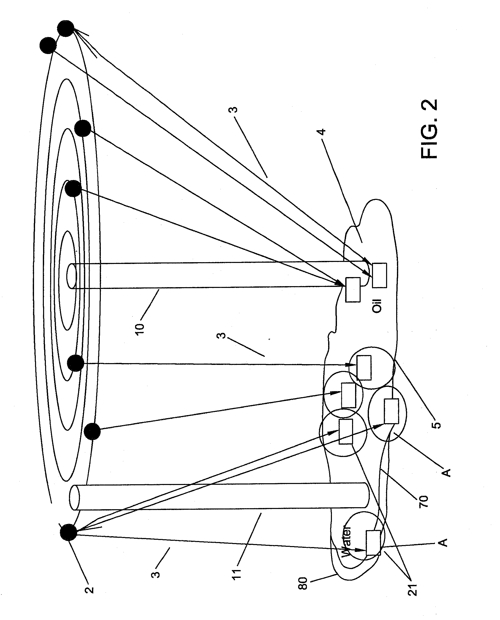
[0013]In another embodiment, a source of electromagnetic energy from an array of antennae transmitting in the far field is provided for imparting pulses at the depth of the fluid reservoir to communicate with nano devices to effect motion of the nano devices.
[0014]In another embodiment, a source of electromagnetic energy from an array of antennae transmitting in the far field is provided for imparting pulses at the depth of the fluid reservoir to communicate with nano sensors and effect a chemical reaction using one or more of the nano devices.
[0015]A communications method for communicating information to nano sensors located within a select subsurface region: from multiple positions on or below the terrain surface and separated from the select subsurface region via geological strata, transmitting immediately in the far field electromagnetic energy beam signals of a predetermined frequency, duration, and power that combine to cover a target area of the select sub surface region; and receiving via one or more nano sensors located in an oil reservoir at the sel...

Problems solved by technology

Eventually, the flow of oil to the well will decrease to a point where the amount of oil available from the well no longer justifies the costs of production, which includes the costs of removing and transporting the oil.

Method used


Image

  • System and method to remotely interact with NANO devices in an oil well and/or water reservoir using electromagnetic transmission
  • System and method to remotely interact with NANO devices in an oil well and/or water reservoir using electromagnetic transmission
  • System and method to remotely interact with NANO devices in an oil well and/or water reservoir using electromagnetic transmission

Examples


Embodiment Construction

[0027]The following description of the preferred embodiments is merely by way of example and is in no way intended to limit the invention, its applications, or uses.

[0028]The invention herein is disclosed in the context of nano technology. Nano additives refer to compositions of matter that include nano particles and / or nanosensors. Nano particles and nano sensors herein are collectively referred to as nano devices. References to nano devices include both singular, plural, ensembles, and colonies of such nano devices. Reference to nano sensor herein generally refers to a molecularly precise functional nanosystem that incorporates one or more nanoscale components that have molecularly precise structures. Note that in any application that refers to a nano device or nanosystem the application may also include active microsensor networks. Reference to passive nano devices or sensors herein generally refer to molecularly precise devices having, among other properties, mobility within the...


PUM


Abstract

The invention provides for electromagnetic transmission and reception used in detecting relative changes associated with nano devices existing within an oil reservoir. The system enables monitoring of the relative movement of the nano devices in the oil and / or water over a given area based on the incremental or relative changes of the intensity of the reflections over time. In one embodiment, a source of electromagnetic energy from an array of antennae transmitting immediately in the far field recharges a power source embedded in the nano devices. In another embodiment, the return signals from the nano devices maps the morphology of ensembles of nano devices. In yet another embodiment the transmission controls the movement of the nano devices and controls the function preformed by the nano devices relative to effecting changes in the well to improve production of oil.

Description

CLAIM FOR PRIORITY[0001]This application claims priority to Provisional Patent Application Ser. No. 61 / 107,494 entitled SYSTEM AND METHOD TO REMOTELY INTERACT WITH NANO DEVICES IN AN OIL WELL AND / OR WATER RESERVOIR USING ELECTROMAGNETIC TRANSMISSION filed Oct. 22, 2008, the subject matter thereof incorporated by reference in its entirety.FIELD OF THE INVENTION[0002]This invention relates generally to subsurface fluid recovery systems, and more particularly, to a system and method that uses an array of Electromagnetic transmitters and receivers for remotely interacting with nano devices.BACKGROUND OF THE INVENTION[0003]The invention herein is drawn to improving the production of oil reserve recovery using communications with smart sensors, remote power delivery for smart sensor networks, reservoir imaging, monitoring and management at the oil well. An oil well is typically drilled hundreds or thousands of feet within various geological strata to reach a permeable formation containing...

Claims


Application Information

Patent Timeline
IPC IPC(8): G01V3/00
CPCE21B47/122E21B47/121E21B47/125E21B47/13
Inventor BENISCHEK, VINCENTCURRIE, MICHAEL
Owner LOCKHEED MARTIN CORP
Learn More