Image display device, image display method, and program product

a display device and image technology, applied in the field of image display devices, image display methods, and program products, can solve the problems of inability to perform full operations, difficulty in operating with the same user interface, and restricted finger movements of operators, so as to achieve the effect of increasing operation efficiency and operation efficiency

Inactive Publication Date: 2010-04-29
FUJIFILM CORP
View PDF3 Cites 103 Cited by
  • Summary
  • Abstract
  • Description
  • Claims
  • Application Information

AI Technical Summary

Benefits of technology

[0030]According to the present invention, the image display device automatically switches to an optimum user interface according to the hold state to change the display content by detecting the usage and the hold state thereof, so that the operator can perform operations while fully enjoying viewing the displayed content with the optimum user interface.
[0031]According to an embodiment of the invention, operation eff

Problems solved by technology

However, when the operator holds a display device in his/her hands to view the displayed image, the finger movements are so restricted as compared with when it is placed on a desk, etc. that the operator often had difficulty in operation with the same user interface as is used when the display device is placed on a desk, etc.
Thus, a key display, added to the displayed content, obstructs the view and makes

Method used


Image

  • Image display device, image display method, and program product
  • Image display device, image display method, and program product
  • Image display device, image display method, and program product

Examples


Embodiment Construction

[0043]The following describes in detail the image display device of the present invention based upon the preferred embodiments illustrated in the accompanying drawings.

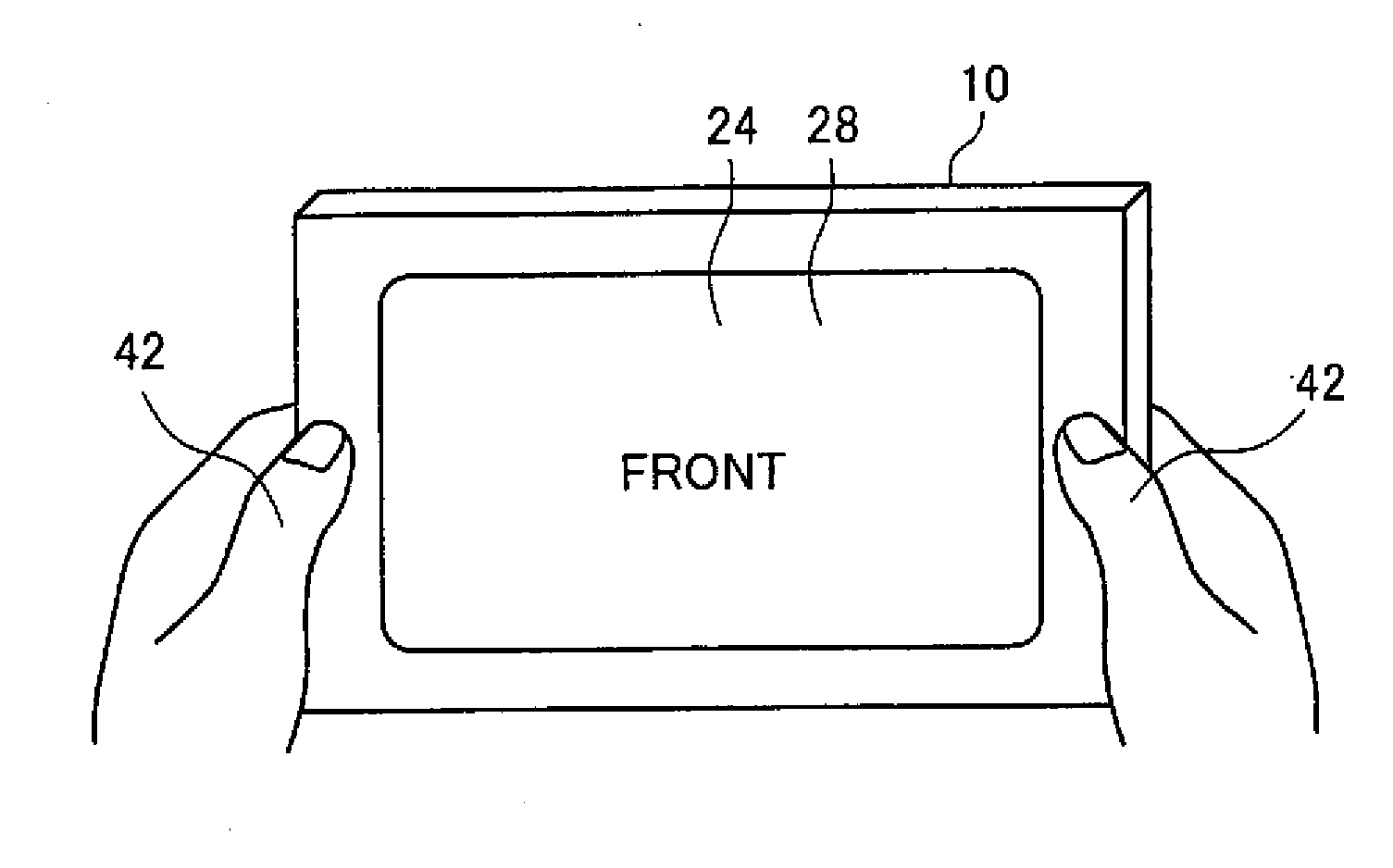
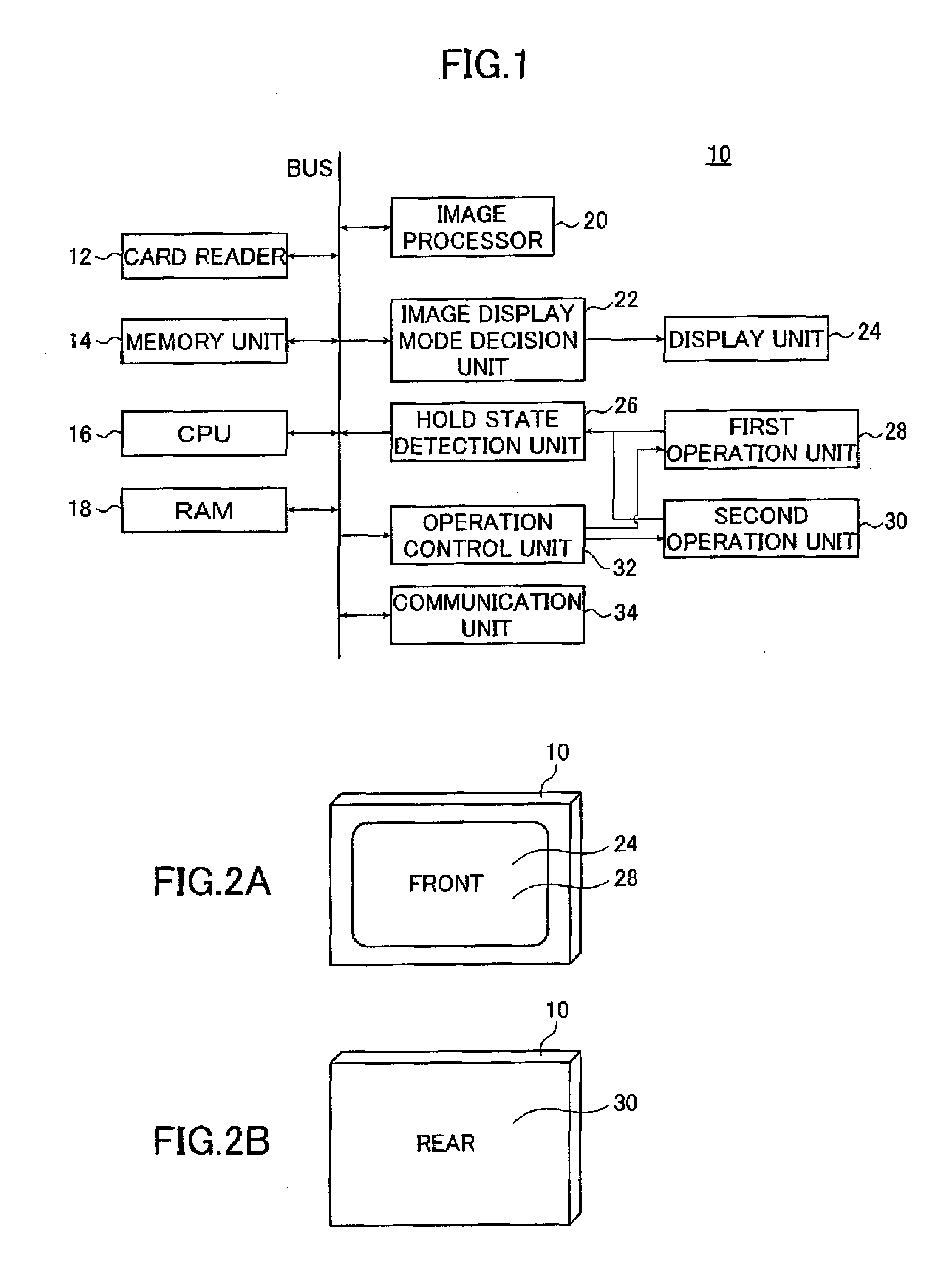
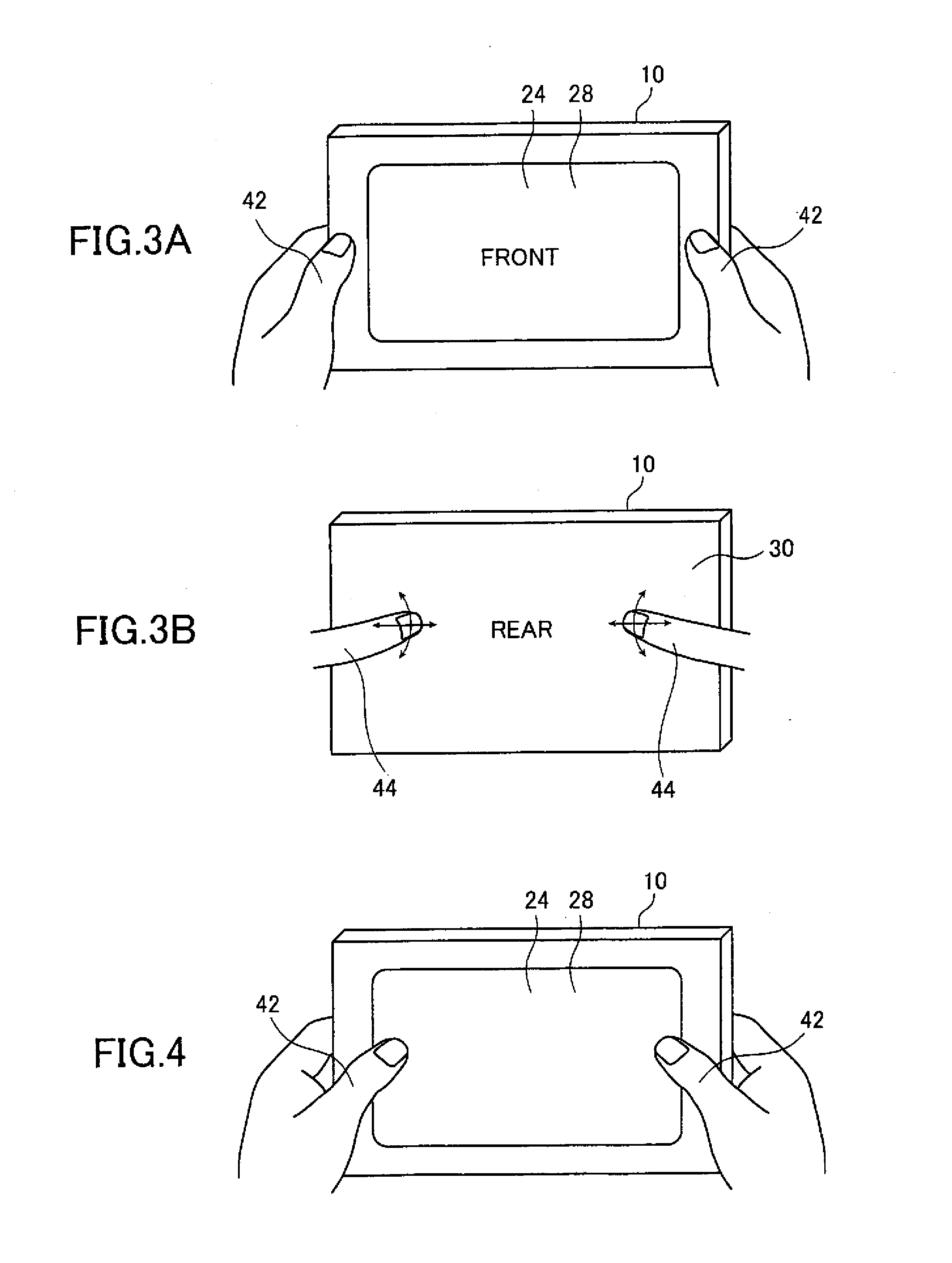
[0044]FIG. 1 is a block diagram illustrating an embodiment of configuration of the image display device according to the invention; FIGS. 2A and 2B are schematic views illustrating external appearances of a DPF 10, which is the image display device of the invention.

[0045]The DPF 10 as the image display device illustrated in FIG. 1 comprises a card reader 12, a memory unit 14, a CPU 16, a RAM 18, an image processor 20, an image display mode decision unit 22, a display unit 24, a hold state detection unit 26, a first operation unit 28, a second operation unit 30, an operation control unit 32, and a communication unit 34.

[0046]The card reader 12 is a means for entering image data, etc. to be displayed on the DPF 10. Through the card reader 12, image data, etc. can be read from an SD memory card, an xD picture card, and t...


PUM


Abstract

An image display device includes a display unit (DU) and an operation screen, a first operation unit on the DU generating an operation signal, a second operation unit on a rear of the DU generating an operation signal, a hold state (HS) detection unit detecting a HS of the image display device, an image display mode decision unit determining an image display mode for displaying the image on the DU according to the HS, an image processor determining a content of the image to be displayed according to the HS, and an operation control unit controlling the first and second operation units according to the HS. A user interface of the DU is changed to a user interface corresponding to the HS by changing, according to the HS, one or more of the image display mode/content of the image, and a method for controlling the first and second operation units.

Description

[0001]The present application claims priority of Japanese Patent Application No. 2008-276974, which is herein incorporated in its entirety by reference. Further, the entire contents of the documents cited in this specification are incorporated herein by reference.BACKGROUND OF THE INVENTION[0002]The present invention relates to an image display device provided with a touch panel on a front side and a touch panel or a touch pad on a rear and / or a lateral side, an image display method, and a program product, providing an optimum user interface corresponding to a hold state of the image display device. This is achieved by changing the image display method, displayed content, and a method of controlling the touch panel or the touch pad according to the hold state of the display device.[0003]Conventionally, a digital photograph frame (referred to also as DPF below), which is one of the image display devices, only provides the same user interface for displaying an image whether the DPF is...

Claims


Application Information

Patent Timeline
IPC IPC(8): G06F3/041G06F3/048G06F3/0488
CPCG06F3/0488
Inventor ONO, RYOYAMAJI, KEI
Owner FUJIFILM CORP
Why Eureka
Try Eureka