Antenna arrangement apparatus, reception apparatus and method reducing a common mode signal

Inactive Publication Date: 2010-04-29
TOMTOM INT BV
View PDF0 Cites 1 Cited by
  • Summary
  • Abstract
  • Description
  • Claims
  • Application Information

AI Technical Summary

Benefits of technology

[0038]According to a fourth aspect of the present invention, there is provided a method of reducing a common-mode signal in respect of an antenna arrangement apparatus, the method comprising: providing a resonant feed-line dipole antenna having a first pole portion and a length of coaxial cable comprising a second pole portion, the length of coaxial cable having a distal end with respect to the first pole portion; and coupling the distal end of the length of coaxial cable to a common-mode filter.
[0040]It is thus possible to provide an apparatus and method that are less susceptible to common-mode signals. Improved signal reception is thus possible, thereby resulting in improved reception of information, for example traffic-related information, such as RDS-TMC data. The structure of the antenna is also simple and economic to manufacture. The use of the common-mode filter isolates the resonant feed-line reception antenna from any common-mode signals induced in a coupling cable between a tuner and a device to which the apparatus can be coupled. Improved isolation of the resonant feed-line antenna from other common-mode signals, for example those resulting from parasitic capacitances of the device to which the apparatus can be coupled, or from power sources, can be achieved. Furthermore, a galvanic connection between the antenna and a chassis of a vehicle is not necessary. Additionally, the apparatus and method are not necessarily application specific and so provide a flexible solution for different RF reception applications. The improved performance provided by the method and apparatus also reduces instances of user annoyance and false enquires made to manufacturers, distributors and / or retailers concerning whether or not the apparatus is faulty.

Problems solved by technology

However, the straight wire type antenna is susceptible to EMC interference from neighbouring electrical and / or electronic devices, for example the PND and / or a power supply, for example a Cigarette Lighter Adaptor (CLA).
Furthermore, it is undesirable, from the perspective of a manufacturer of a PND, to require a user of the PND to connect an antenna to the body of the vehicle in order to obtain the desired “clean” ground reference.
Consequently, antenna performance can, in some circumstances, be inadequate resulting in the PND not receiving any data or only partial data.
From the perspective of a user of the PND, the user simply perceives that no or incomplete traffic information is available and can wrongly conclude that the PND and / or the TMC accessory are / is malfunctioning.
An interference-free analogue to the ground is not, unfortunately, available in the context of the RDS-TMC tuner and antenna.
However, such solutions are expensive and can result in other problems relating to, for example, heat dissipation.
Hence, design and implementation costs and lack of re-usability of an electromagnetic radiation shielding solution makes electromagnetic shielding of the external sources of electromagnetic radiations undesirable.

Method used


Image

  • Antenna arrangement apparatus, reception apparatus and method reducing a common mode signal
  • Antenna arrangement apparatus, reception apparatus and method reducing a common mode signal
  • Antenna arrangement apparatus, reception apparatus and method reducing a common mode signal

Examples


Embodiment Construction

[0049]Throughout the following description identical reference numerals will be used to identify like parts.

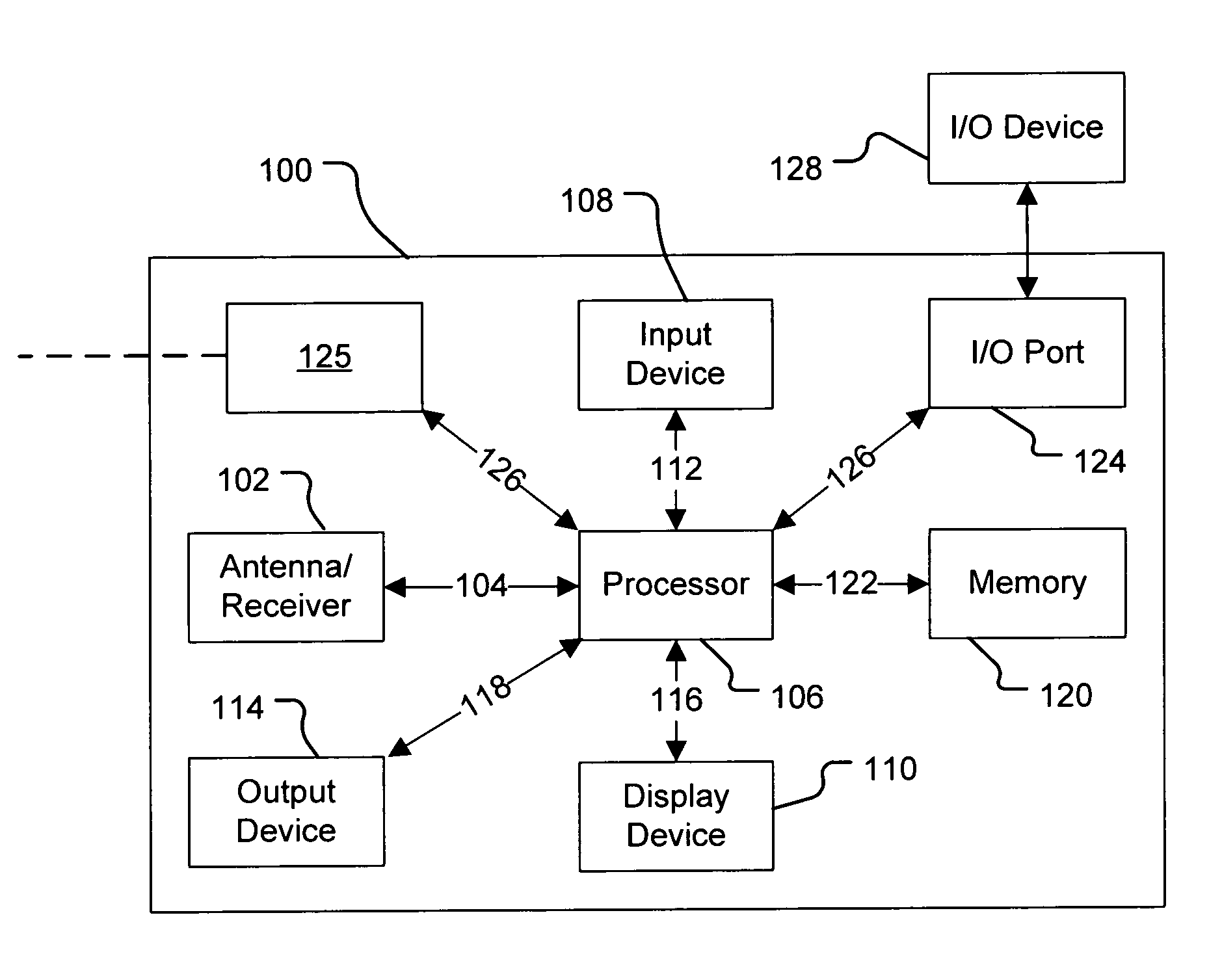
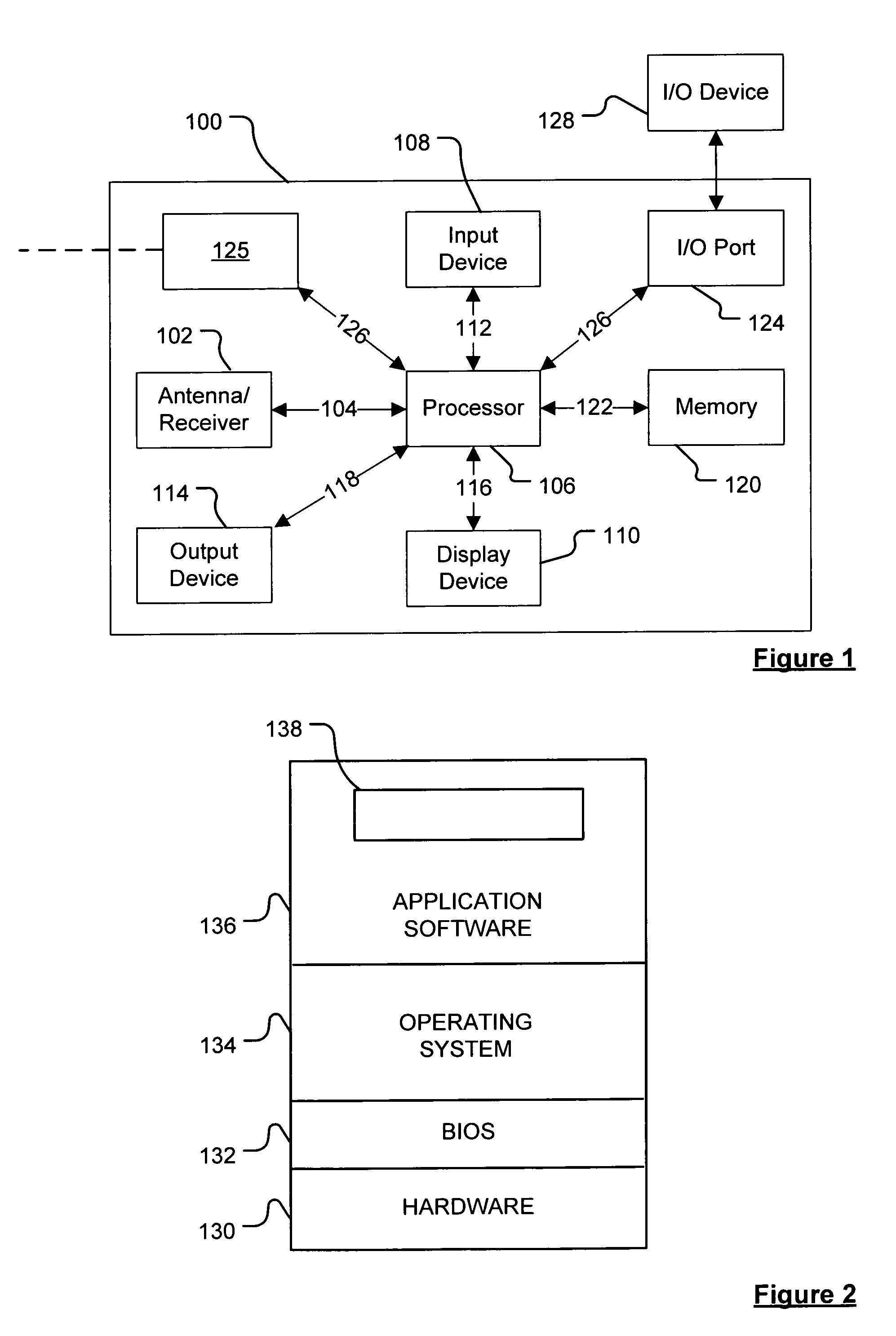
[0050]Embodiments of the present invention will now be described with particular reference to a PND. It should be remembered, however, that the teachings of the present invention are not limited to PNDs but are instead universally applicable to any type of processing device, for example but not limited to those that are configured to execute navigation software in a portable or mobile manner so as to provide route planning and navigation functionality. It follows therefore that in the context of the present application, a navigation device is intended to include (without limitation) any type of route planning and navigation device, irrespective of whether that device is embodied as a PND, a vehicle such as an automobile, or indeed a portable computing resource, for example a portable personal computer (PC), a mobile telephone or a Personal Digital Assistant (PDA) executing rou...


PUM


Abstract

An antenna arrangement apparatus includes a resonant feed-line dipole reception antenna having a first pole portion and a length of coaxial cable. The length of coaxial cable includes a second pole portion. The apparatus also includes a common-mode filter. In at least one embodiment, the length of coaxial cable has a distal end with respect to the first pole portion, the distal end being coupled to the common-mode filter.

Description

FIELD OF THE INVENTION[0001]The present invention relates to an antenna arrangement apparatus of the type that, for example, is used to receive Radio Frequency signals for an electronic device, for example a navigation device or a communications device. The present invention also relates to a receiver apparatus of the type that, for example, is used to receive the Radio Frequency signals for an electronic device, for example a navigation device or a communications device. The present invention further relates to a method of reducing a common-mode signal, the method being of the type that, for example, is used to receive a Radio Frequency signal in the presence of a common-mode current generated by an external source.BACKGROUND TO THE INVENTION[0002]Portable computing devices, for example Portable Navigation Devices (PNDs), which include GPS (Global Positioning System) signal reception and processing functionality are well known and are widely employed as in-car or other vehicle navi...

Claims


Application Information

Patent Timeline
IPC IPC(8): H04B1/06H01Q9/16H01Q1/24
CPCH01Q9/16
Inventor VAN DEN ELZEN, JAN
Owner TOMTOM INT BV
Why Eureka
Try Eureka