
Device for low-pressure casting, a method for filling inert gas in the device, and method for producing a cast

a low-pressure casting and gas-filled technology, applied in the direction of manufacturing tools, foundry patterns, moulding apparatus, etc., can solve the problems of complex structure, deterioration of productivities and efficiencies, and longer time for each cycle of casting

Inactive Publication Date: 2010-05-06
SINTOKOGIO LTD
View PDF2 Cites 11 Cited by
  • Summary
  • Abstract
  • Description
  • Claims
  • Application Information

AI Technical Summary

Benefits of technology

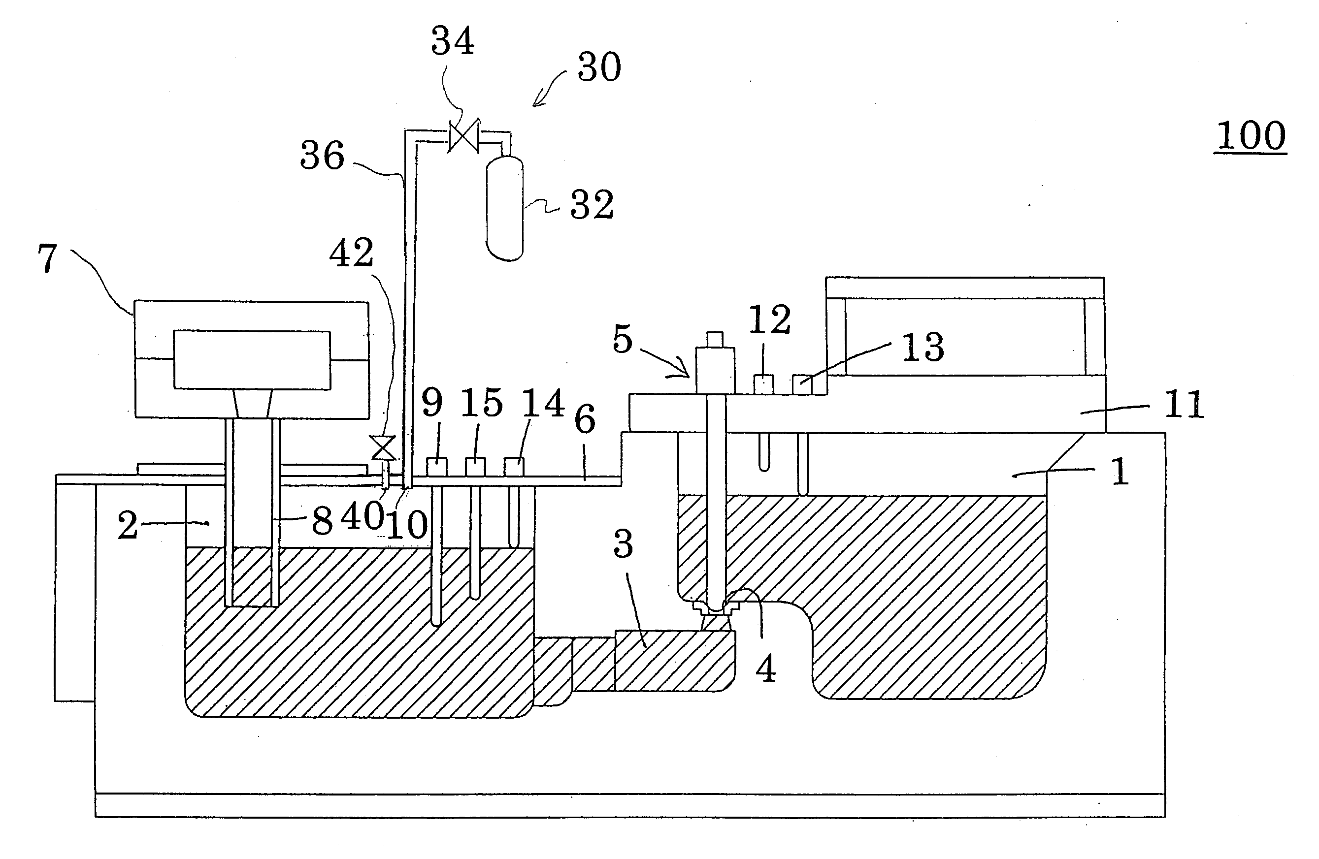
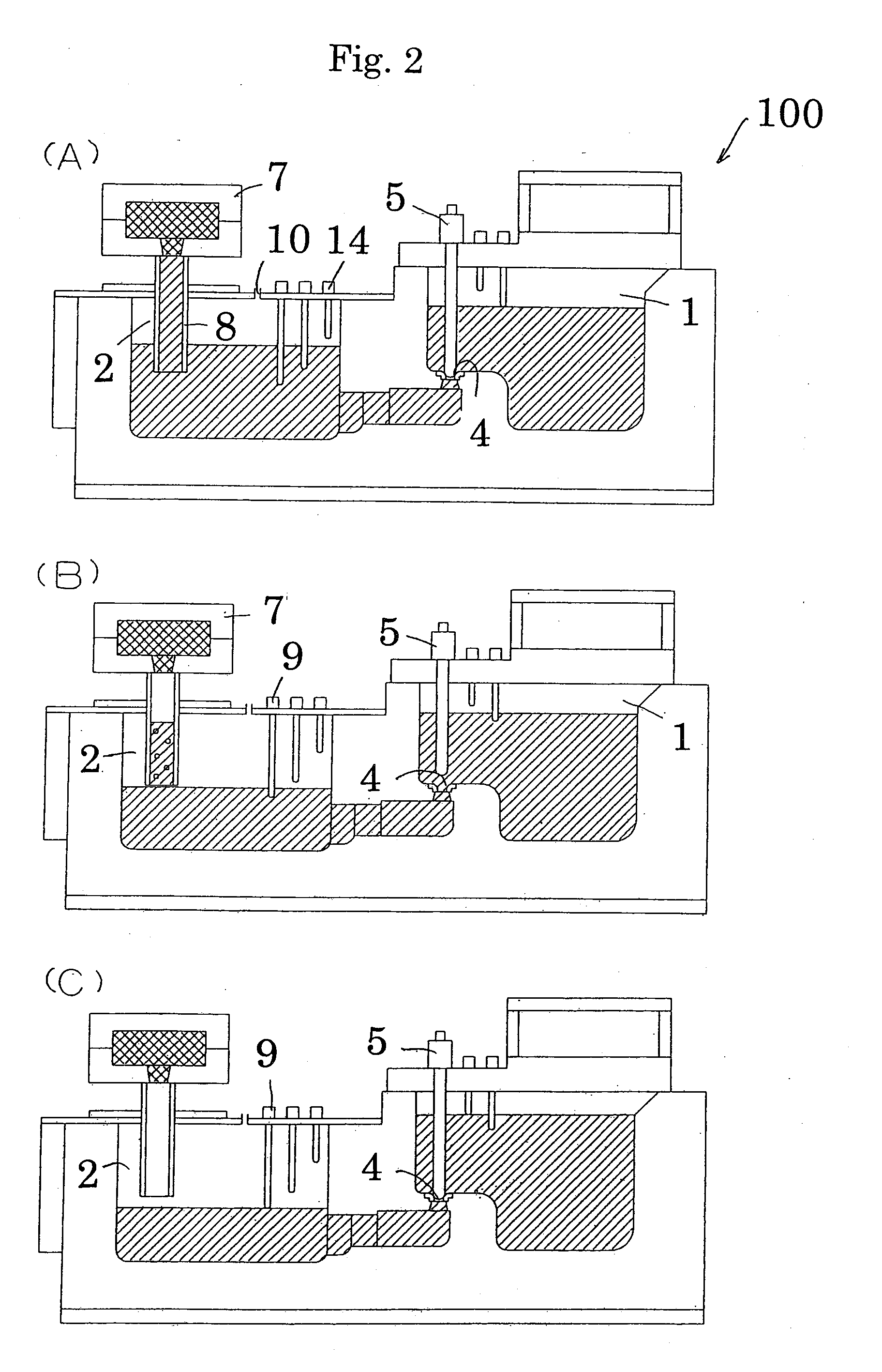
[0007]As described above, in the present invention the molten metal is filled in the mold by pressurizing the surface of the molten metal with inert gas in the pressurizing room. After solidifying the molten metal filled in the mold, the molten metal in the pressurizing room is returned to the room for holding it by opening the hole for communication by the on-off valve. The sensing means is installed to sense the communication between the space over the molten metal in the pressurizing room and the stalk or the guiding hole. Thus the inert gas in the pressurizing room can definitely flow into the stalk or the guiding hole, since the space over the molten metal in the pressurizing room communicates with the stalk or the guiding hole. Therefore, to prevent oxidized metal from forming on the molten metal in the stalk or the guiding hole, the surface of the molten metal in the stalk or the guiding hole is not exposed to air. The present invention has such advantageous effects.
[0008]The basic Japanese patent applications, No. 2007-106639, filed Apr. 16, 2007, and No. 2007-157055, filed Jun. 14, 2007, are hereby entirely incorporated by reference into the present application. The present invention will become more fully understood from the detailed description given below. However, the detailed description and the specific embodiment are only illustrations of desired embodiments of the present invention, and are given only for an explanation. Various possible changes and modifications will be apparent to those of ordinary skill in the art on the basis of the detailed description. The applicant has no intention to dedicate to the public any disclosed embodiment. Among the disclosed changes and modifications, those which may not literally fall within the scope of the present claims constitute, therefore, a part of the present invention in the sense of the doctrine of equivalents. The use of the articles “a,”“an,” and “the” and similar referents in the specification and claims are to be construed to cover both the singular and the plural, unless otherwise indicated herein or clearly contradicted by the context. The use of any and all examples, or exemplary language (e.g., “such as”) provided herein, is intended merely to better illuminate the invention, and so does not limit the scope of the invention, unless otherwise claimed.

Problems solved by technology

However, in the conventional device for low-pressure casting with the above structure, the time for each cycle of casting gets longer and the productivities and efficiencies deteriorate, since the holding furnace must go up and down for each replacement of air with non-oxidizing gas in the holding furnace, the stalk, and the mold.
Moreover, its structure is complicated.
In addition, it is difficult to keep a seal between the cover of the holding furnace and the stalk.
These are the problems.

Method used


Image

  • Device for low-pressure casting, a method for filling inert gas in the device, and method for producing a cast
  • Device for low-pressure casting, a method for filling inert gas in the device, and method for producing a cast
  • Device for low-pressure casting, a method for filling inert gas in the device, and method for producing a cast

Examples


first embodiment

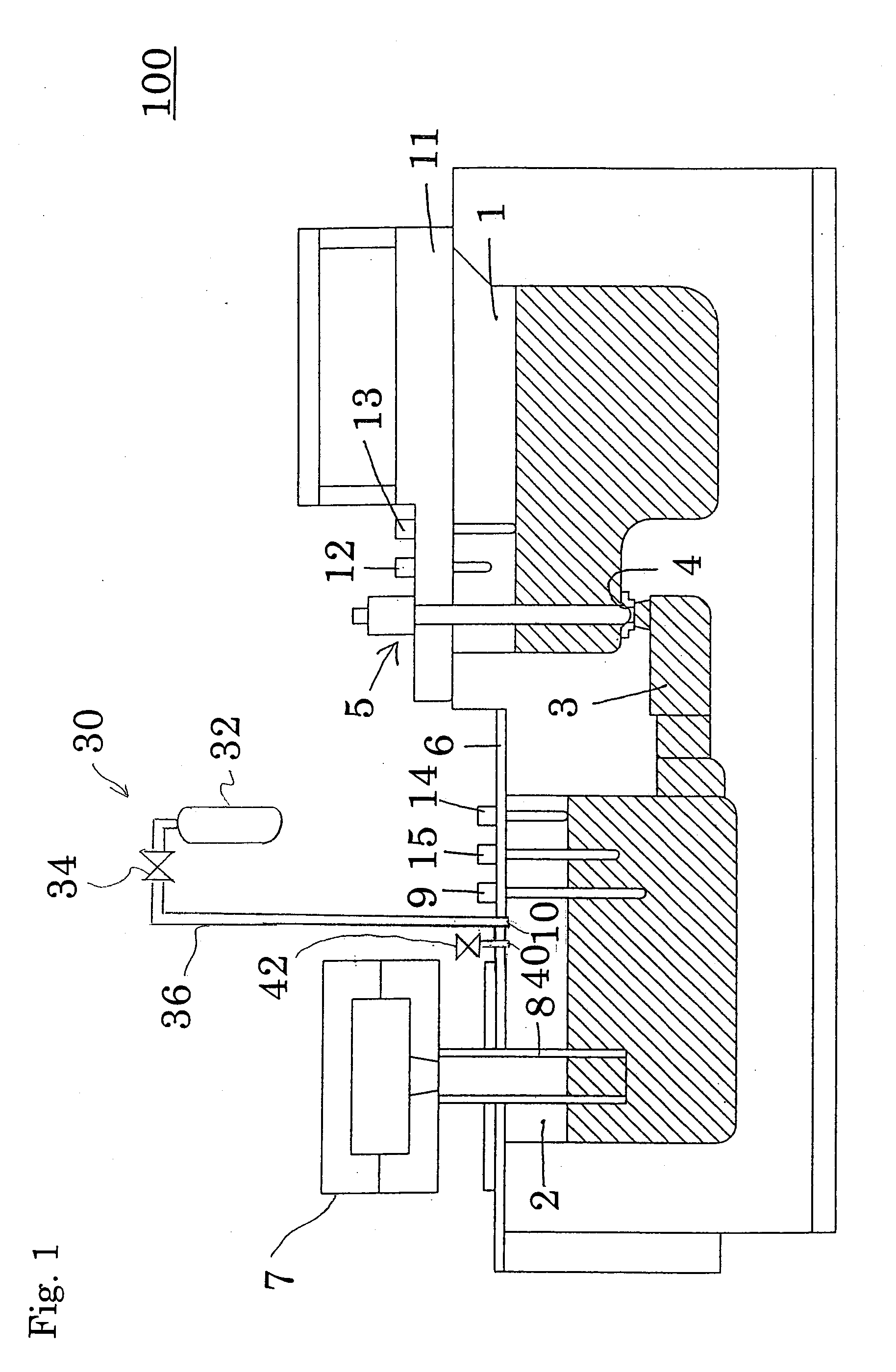
[0016]The first four embodiments of the device for low-pressure casting of the present invention will now be described in detail based on FIGS. 1-7. As the first embodiment, the device for low-pressure casting 100, which has a level sensor 9 as the sensing means, is described. As shown in FIG. 1, it comprises a room for holding molten metal 1, a pressurizing room 2 for pressurizing molten metal by inert gas, an on-off valve 5 for opening and shutting a hole for communication 4 to communicate between the room for holding molten metal 1 and the pressurizing room 2 through an auxiliary room 3, a cover 6 for shutting the upper-end opening of the pressurizing room 2 and sealing it, a stalk 8 suspended from a gate for pouring of a mold 7, the level sensor 9 for sensing the level of the surface of the molten metal in the pressurizing room 2, and a means 30 for supplying inert gas to the upper part of the pressurizing room 2. The pressurizing room 2 is configured to communicate with the roo...

third embodiment

[0029]Next, in reference to FIG. 5, the device for low-pressure casting 110 as the third embodiment is described. As shown in FIG. 5, the device for low-pressure casting 110 comprises a pressure sensor 19 in place of the level sensor 9 of the device for low-pressure casting in FIG. 1. The pressure sensor 19 is supported by the cover 6 and senses the pressure in the pressurizing room 2.

[0030]As a level sensor in the pressurizing room 2, the level sensor 14 for sensing the upper limit of the level of the molten metal in the pressurizing room 2 is installed. Both the electro-magnetic on-off valve 42 and the on-off valve 34, either of which can control the pressure of the inert gas in the pressurizing room 2, as described in regards to the device for low-pressure casting 100, function as a means for controlling the pressure. The means for controlling the pressure controls the pressure in the pressurizing room 2 based on the pressure measured by the pressure sensor 19 or any other pressu...


PUM

PropertyMeasurementUnit
Pressureaaaaaaaaaa

Abstract

The object of the present invention is to provide a device for low-pressure casting wherein the stalk or the guiding hole is filled with inert gas by causing the space formed over the molten metal in the pressurizing room to communicate with the stalk or the guiding hole. The device for low-pressure casting (100) wherein molten metal is supplied into a mold through a stalk (8) suspended from a gate for pouring of the mold (7) or through a guiding hole connected to the gate for pouring at one end by pressurizing the molten metal by inert gas, the device comprising: a room for holding molten metal (1); a pressurizing room (2) to be in communication with the room for holding molten metal through a hole for communication (4), wherein a bottom end of the stalk (8) enters the pressurizing room or another end of the guiding hole is connected to the pressurizing room, and wherein the molten metal is pressurized by inert gas; an on-off valve (5) for opening and shutting the hole for communication; a sensing means (15) for sensing that the space over the molten metal in the pressurizing room communicates with the stalk or the guiding hole; and a means (30) for supplying inert gas to an upper part of the pressurizing room.

Description

TECHNICAL FIELD[0001]The present invention relates to a device for low-pressure casting, a method for filling inert gas in the device, and a method for producing a cast.BACKGROUND ART[0002]Conventionally a device for low-pressure casting has been proposed. The device does not have a complicated structure. It allows air in a mold, a tube for casting (a stalk), and a holding furnace to be effectively replaced with non-oxidizing gas. The device comprises a holding furnace that is sealed almost airtightly, a means for supplying non-oxidizing gas to the holding furnace, a stalk by which the holding furnace communicates with a mold, and a means for switching the opening of the stalk at the holding furnace side to the position for casting or to the position for replacing a mold. At the position for casting, the opening is immersed in molten metal. At the position for replacing, at least a part of the opening is over the surface of the molten metal in the holding furnace. Non-oxidizing gas ...

Claims


Application Information

Patent Timeline
IPC IPC(8): B22D46/00B22D2/00B22C9/00B22D18/04B22D25/00
CPCB22D18/04B22D18/08
Inventor MIZUNO, SHINYAMURATA, YUTAKA
Owner SINTOKOGIO LTD
Learn More