Dual independent push button rotary knob assembly

a rotary knob and push button technology, applied in the direction of mechanical control devices, process and machine control, instruments, etc., can solve the problems of complicated assembly of the housing, difficult replacement of the control knob, and complicated assembly or maintenance of the control knob

Active Publication Date: 2010-05-06
ELBIT SYSTEMS OF AMERICA LLC
View PDF17 Cites 24 Cited by
  • Summary
  • Abstract
  • Description
  • Claims
  • Application Information

AI Technical Summary

Benefits of technology

[0007]To meet this and other needs, and in view of its purposes, the present invention provides a knob assembly including two encoders disposed internally within a housing and dual independent push button rotary knobs, containing two magnets, disposed externally to the housing. An interface plate of the housing is interposed between the encoders and the knob assembly and physically isolates the interior of the housing from the dual independent rotary knobs. The interface plate prevents environmental leakage and electromagnetic interference from entering the housing.
[0009]Another embodiment of the present invention provides a control unit including a knob assembly. The knob assembly includes two encoders disposed internally within a housing and a knob assembly, containing two magnets, disposed externally to the housing. An inner rotary knob functions as both a rotary knob, providing rotational movement, and as a push button, providing axial translation. An outer rotary knob provides independent rotational movement from the inner rotary knob. The push button may be depressed independently of any rotational movement to either of the rotary knobs. A boundary surface of the housing is interposed between the encoders and the knob assembly and physically isolates the interior of the housing from the dual independent push button rotary knob assembly. The boundary surface prevents environmental leakage and electromagnetic interference from entering the housing. The encoders are configured to decode the angular orientation of the two rotary knobs and the axial translation of the inner push button rotary knob.

Problems solved by technology

While enabling multiple control functions of the electronics in the housing, the conventional rotary-push button control complicates the assembly of the housing and makes replacement of the control knob difficult.
The protrusion creates an opening into the housing which may allow environmental contamination and electromagnetic interference (EMI) into the electronics.
This, in turn, may be messy and may further complicate the assembly or maintenance of the control knob.

Method used


Image

  • Dual independent push button rotary knob assembly
  • Dual independent push button rotary knob assembly
  • Dual independent push button rotary knob assembly

Examples


Embodiment Construction

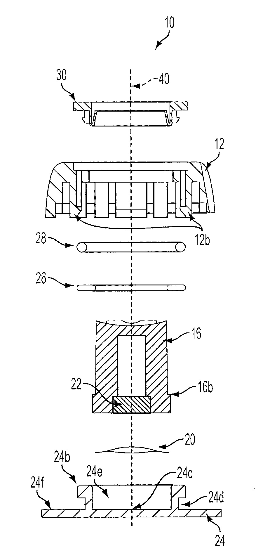
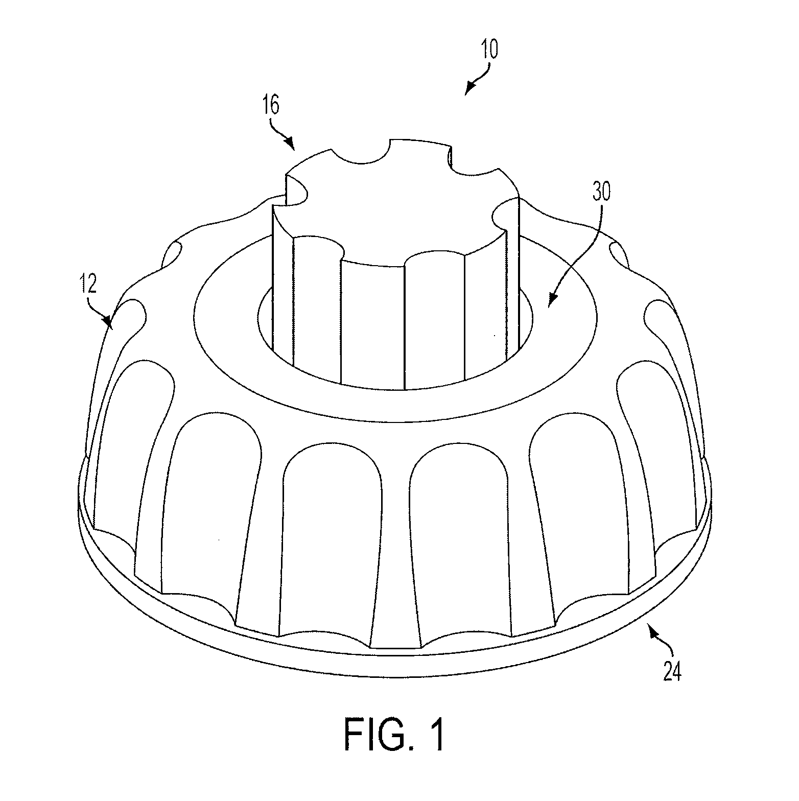
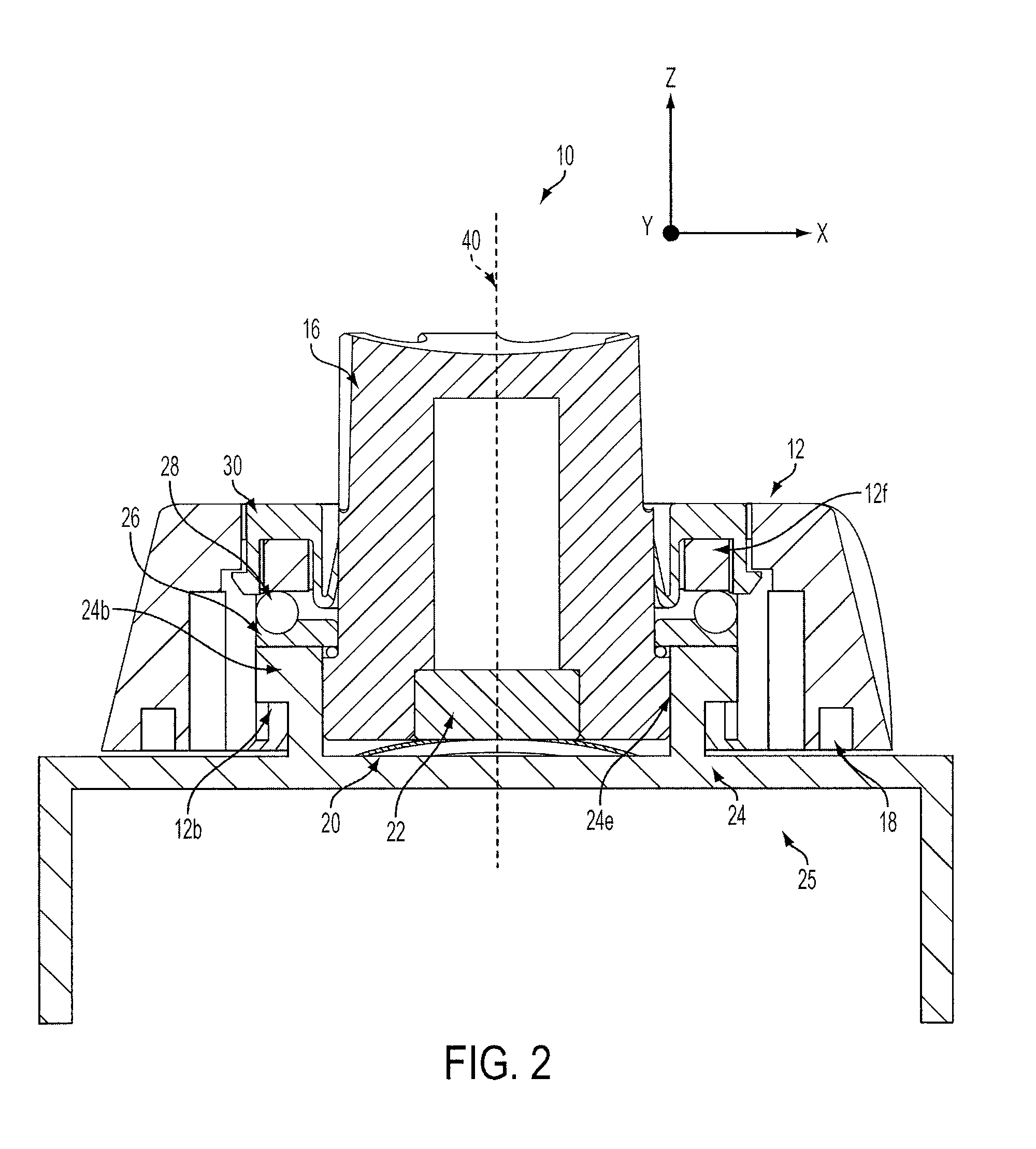
[0018]The present invention includes a push button dual-independent rotary knob assembly. As will be explained, the knob assembly provides rotational movement and translational travel along an axis. Unlike conventional knobs and switches, the present invention controls electronics within a housing, without requiring protrusion into the housing. Also unlike conventional knobs and switches, the present invention enables contactless multi-function control through the use of two independent rotary knobs. The components of the present invention may operate without need for O-rings, gaskets, or any other applied sealants between the knob assembly and the housing.

[0019]The push button rotary knob assembly of the present invention offers many advantages, because no portion of the rotary knob protrudes through the housing. For example, (1) there is no leakage path into the housing where environmental contamination or electromagnetic interference (EMI) may enter; (2) the internal volume of th...


PUM


Abstract

The present invention includes a knob assembly which provides rotational movement and translational travel along an axis of dual and independent rotary knobs. The present invention controls electronics within a housing, without requiring protrusion into the housing. Having no protrusions into the housing avoids exposure of the electronics within the housing to environmental contaminants or electromagnetic interference. The components of the dual independent push button rotary knob assembly may operate without need for O-rings, gaskets, or any other applied sealants to prevent containments from entering the housing. Assembly of the knob assembly is simplified, because the rotary knob assembly may be installed and replaced without any tools and without need to access the interior of the housing. Furthermore, if any part of the assembly is damaged, the rotary knob assembly, in part or whole, may be replaced without compromising any seal provided to the exterior surfaces of the housing.

Description

RELATED APPLICATIONS[0001]The present application is a Continuation-In-Part of U.S. patent application Ser. No. 12 / 246,743 filed Oct. 7, 2008, which is incorporated herein by reference in its entirety.FIELD OF THE INVENTION[0002]The present invention relates, in general, to a knob assembly. More specifically, the present invention relates to a dual independent push button rotary knob assembly which provides contactless control of an electronic device residing in a housing, without direct physical contact with the interior of the housing.BACKGROUND OF THE INVENTION[0003]In many electronic housings, in which space is at a premium, control functions are often consolidated in a single control knob. For example, a rotary knob which has several rotational positions for activating several electronic functions may be combined with a push button switch, which may have only one function for turning the electronics on / of functions. While enabling multiple control functions of the electronics i...

Claims


Application Information

Patent Timeline
Patent Type & Authority Applications(United States)
IPC IPC(8): H01H19/00
CPCG01D5/145G01D5/244G01D11/245G05G1/10G05G25/04H01H2019/143
Inventor TRUDEAU, TIMOTHY KRAHNBANDY, GREGORY SEITH
Owner ELBIT SYSTEMS OF AMERICA LLC
Why Eureka
Try Eureka