Charged-particle optical system with dual loading options

a technology of optical systems and charged particles, applied in the direction of instruments, heat measurement, machines/engines, etc., can solve the problems of complex machinery at the tip, high cost of specimen holders for charged-particle optical systems, and general delicate process of loading specimens into charged-particle optical systems, so as to maintain the flexibility of operation.

Active Publication Date: 2010-05-06
FEI CO
View PDF12 Cites 6 Cited by
  • Summary
  • Abstract
  • Description
  • Claims
  • Application Information

AI Technical Summary

Benefits of technology

[0012]The inventors therefore propose a more convenient configuration of a charged-particle optical system suitable for replacing specimens using an in situ specimen holder configured for accepting a cartridge with a specimen, and for replacing specimens using a holder that is removed in its entirety.
[0013]More specifically, the invention relates to a charged-particle optical system comprising an evacuable chamber with a space for accommodating a specific one of multiple specimens in operational use of the charged-particle optical system. The system has a loader, which includes guiding means for controllably guiding a part into and out of the space. The part is configured for enabling to attach a carrier, brought from outside the chamber, to a first specimen holder or to detach the carrier from the first specimen holder and to remove the carrier from inside the chamber. The carrier is configured for accommodating a first one of the specimens. The system also has an interface in the chamber for removably accommodating and positioning, in operational use of the system, the first specimen holder or a second specimen holder with a second one of the specimens mounted thereon.
[0014]Accordingly, the charged-particle optical system in the invention allows loading a specimen on a cartridge or other carrier that has to be attached to a holder already in place in the system, as well as loading a specimen already mounted on a holder by means of placing the holder. Changing between these types of holders does not require additional service actions from the operator. The system in the invention thus maintains its operational flexibility in that it can be used to support all types of experiments at high specimen temperatures, at low specimen temperatures, using straining the specimen, etc. Note that in the electron microscope disclosed in U.S. Pat. No. 5,986,270 the specimen holder moves to or from the loader unit, whereas in the invention the loader accommodates a part that moves to the stationary holder or away from the stationary holder. The cartridge loading cycle in the invention does therefore not interfere with positioning the holder.

Problems solved by technology

This needs intricate machinery at the tip.
All this shows that specimen holder assemblies for charged-particle optical systems are expensive components.
The inventors have realized that loading a specimen into a charged-particle optical system is generally a delicate process.
The specimen can be damaged during mounting and / or during the loading of the holder into the charged-particle optical system.
Owing to the amount of space available for maneuvering, as a result of part of the transport unit and part of the cooling means extending into the object space, the setup disclosed in U.S. Pat. No. 5,986,270 is not suitable for replacing specimens by means of replacing specimen holders.
Also, U.S. Pat. No. 5,986,270 is not suitable for replacing specimens by means of replacing the specimen holder, as the removal and re-insertion interferes with thermal equilibrium requirements, discussed above.

Method used


Image

  • Charged-particle optical system with dual loading options
  • Charged-particle optical system with dual loading options
  • Charged-particle optical system with dual loading options

Examples


Embodiment Construction

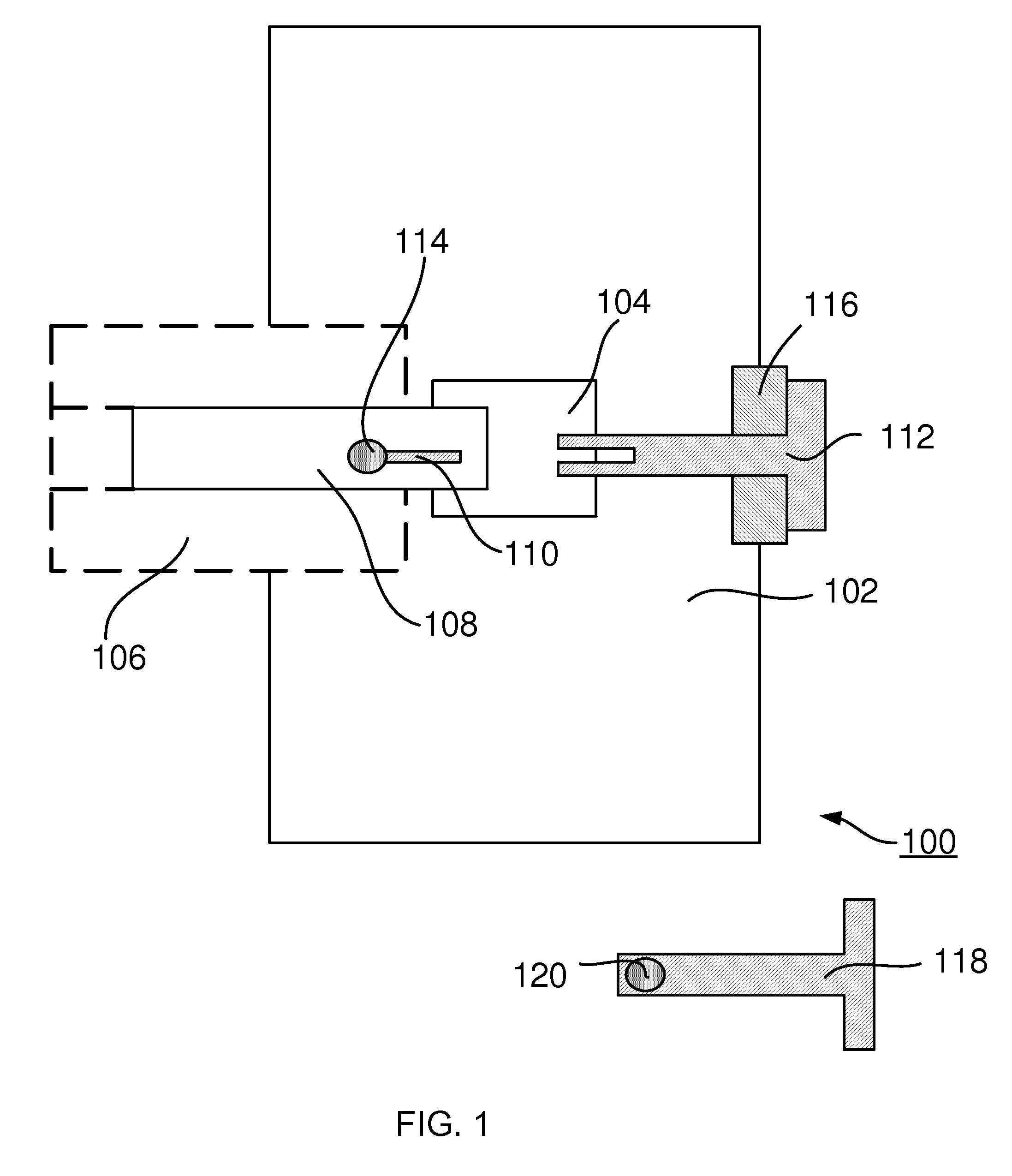
[0022]FIG. 1 is a block diagram of a charged-particle optical system 100 of the invention. As charged-particle optical systems are well known in the art, FIG. 1 only shows those components that are relevant to the current invention.

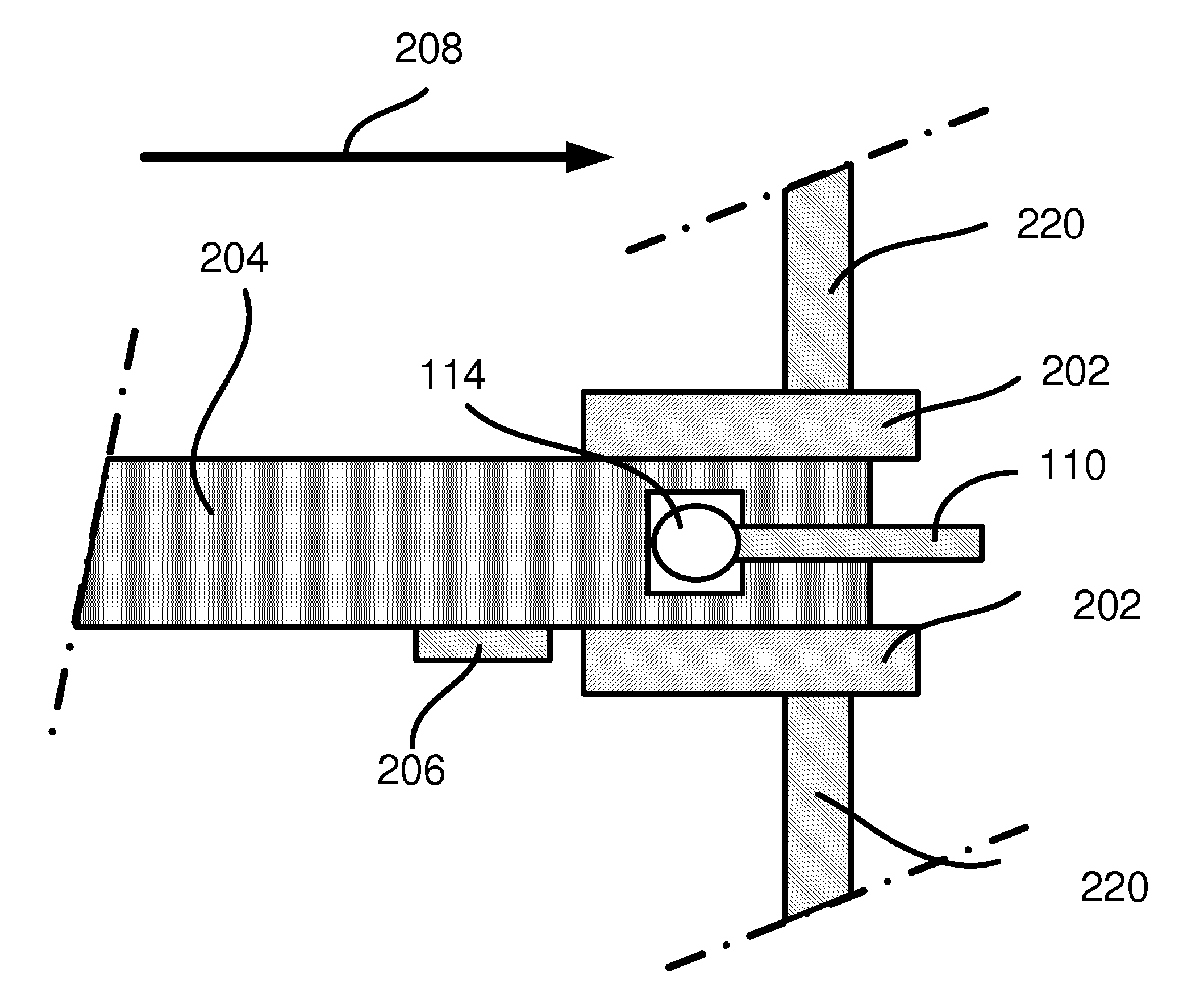
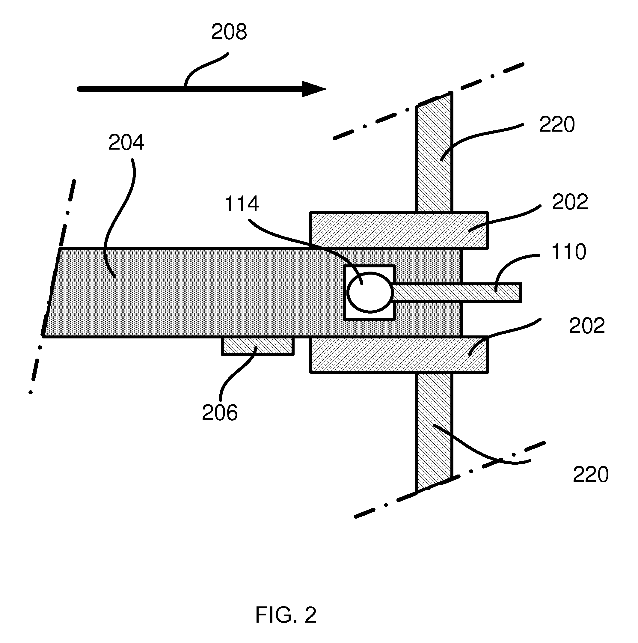
[0023]Charged-particle optical system 100, e.g., a TEM or a STEM, comprises an evacuable chamber 102, coupled to vacuum pump (not shown) and having a space 104 for accommodating a specific one of multiple specimens in operational use of charged-particle optical system 100. System 100 also has a loader 106. Loader 106 accommodates a part 108 that is moveable into and out of space 104. Part 108 is configured for enabling to attach a carrier 110, brought from outside charged-particle optical system 100, or from outside chamber 102, to a first specimen holder 112 or to detach carrier 110 from first specimen holder 112 and remove carrier 110 from inside chamber 102, or from inside system 100. Carrier 110 is configured for accommodating a first one 114 of the s...


PUM

PropertyMeasurementUnit
temperaturesaaaaaaaaaa
SEMaaaaaaaaaa
Reflection Electron Microscopesaaaaaaaaaa

Abstract

A charged-particle optical system (100) such as an electron microscope has a vacuum chamber (102) with a space (104) for accommodating a specific one (114) of multiple specimens in operational use. The charged-particle optical system has a loader (106) with a part (108) that is moveable into and out of the space. The part is configured for attaching a specimen carrier (110), brought from outside the system, to a first holder (112) or to detach the carrier from the first holder and to remove the carrier from inside the system. The carrier accommodates a first specimen. The system has an interface (116) in a wall of the chamber for removably accommodating the first holder (112) or a second holder (118) with a second specimen (120) mounted thereon.

Description

FIELD OF THE INVENTION[0001]The invention relates to a charged-particle optical system and to a loader for loading a specimen carrier into the system.BACKGROUND ART[0002]Charged-particle optical systems are well known, highly specialized tools for illuminating a specimen with charged particles, e.g., electrons or ions in order to create an image or to modify a surface of the specimen. Different configurations of such tools are referred to by their respective names in the jargon, such as Transmission Electron Microscopes (TEMs), Scanning Electron Microscopes (SEM), Reflection Electron Microscopes (REMs), Scanning Transmission Electron Microscopes (STEMs), Focused Ion Beam apparatus, etc. The compartment wherein the specimen is being illuminated is kept evacuated to a sufficiently low pressure so as to prevent the charged particles from being scattered. Electromagnetic or electrostatic lenses are used to control and collimate the charged-particle beam. The specimen is placed, typicall...

Claims


Application Information

Patent Timeline
Patent Type & Authority Applications(United States)
IPC IPC(8): G01N35/10
CPCH01J37/185H01J37/26H01J2237/184H01J2237/2001H01J2237/202H01J2237/204Y10S977/854
Inventor OETELAAR, JOHANNES ANTONIUS MARIA VEN DENHERMKENS, JORNDONA, PLEUNNEDERLOF, FRANKWONDERGEM, WIM
Owner FEI CO
Why Eureka
Try Eureka